2.1 Student Design Center (SDC) and Laboratory Setup Description
![]() Figure 3 shows in details the cabinet with the power supply, the DC motor and dynamometer. Note that a tachometer is used to measure the motor speed, however the motor speed is also available through the SDC. In fact an encoder is used to sense the position of the rotor, the position is in turn converted into speed information by the FPGA.
Figure 3 shows in details the cabinet with the power supply, the DC motor and dynamometer. Note that a tachometer is used to measure the motor speed, however the motor speed is also available through the SDC. In fact an encoder is used to sense the position of the rotor, the position is in turn converted into speed information by the FPGA.
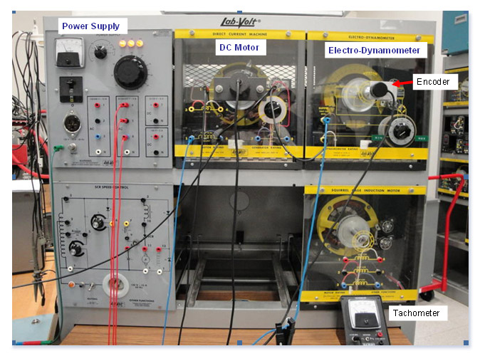
Figure 3: Power supply, DC motor and dynamometer cabinet