Code CS/Rp, Naval Postgraduate School
Monterey, California 93943This paper appeared in Logo in the Schools, 2, 2/3, Summer/Fall 1985, 219-240.
Trigonometry can be a difficult subject for which to motivate students. Sines and tangents have many applications in science and engineering, but it is hard to find situations in the students' own experiences where they are relevant. I suggest a way to use the computer to provide an environment where sines and tangents are important, while at the same time having a natural, intuitive physical meaning. This environment is one where we wish to simulate one simple aspect of three-dimensional objects on a two-dimensional display terminal, namely what happens when they rotate relative to an observer. The environment also provides students with some introduction to three-dimensional graphics.
This material is inteded for use with secondary-school students. It has been tested with ninth graders in a setting of individual tutoring. This work was done at the then-existing Logo Project of the Artificial Intelligence Laboratory of the Massachusetts Institute of Technology. The students did not have any special mathematics background, but had approximately six weeks of experience in programming in the language Logo. The material here encountered only involves the most elementary aspects of trigonometry, and thus is quite accessible to many ninth graders.
What follows is an account of one way a student might be talked through the material. It can be used by a teacher speaking to a class, or can be used directly by students as independent study material. My presentation is deliberately colloquial, reflecting my way of speaking to students, and other teachers may prefer other styles of presentation. Bugs are featured, illustrating the importance of successive debugging and successive refinement in programming. Even though future students may not encounter all these same bugs, they are likely to encounter most of them. I conclude with some project suggestions for the better students.
The programs here are written for the Terrapin (MIT) Apple Logo dialect of Logo. Slight modifications may be necessary to run with other dialects. A built-in cosine (COS) function is required, however, so these programs may not work for Logos on very small machines.
The work reported in this paper was supported in part by the National Science Foundation under grant number EC40708X, and in part by the Foundation Research Program of the Naval Postgraduate School with funds provided by the Chief of Naval Research.
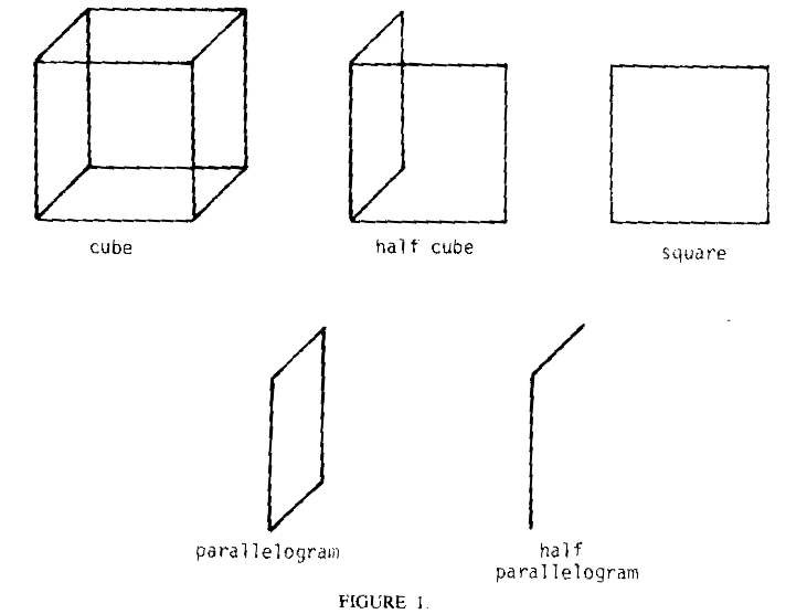
Consider the problem of trying to get LOGO to draw a cube on the display screen. We could say, for example:
TO CUBE
   HALFCUBE
   HALFPGRAM
   LT 90
   FD 100
   RT 90
   HALFCUBE
END

TO HALFCUBE
   SQUARE
   PARALLELOGRAM
END

TO SQUARE
   POLY 100 90
END

TO POLY :SIDE :ANGLE
   MAKE "HEAD HEADING
   POLYREC :SIDE :ANGLE
END

TO POLYREC :SIDE :ANGLE
   FD :SIDE
   RT :ANGLE
   IF(HEADING = :HEAD) STOP
   POLYREC :SIDE :ANGLE
END

TO PARALLELOGRAM
   HALFPGRAM
   HALFPGRAM
END

TO HALFPGRAM
   FD 100
   RT 60
   FD 86
   RT 120
END

This program works OK as far as drawing all the lines of the cube, but it does have to retrace some of these lines in order to reach others. Worse, it's very hard to figure out how to redraw the figure as the cube "rotates" in space. You might say, "Well, this is strange because the cube is basically a nice symmetrical object. Why is it so hard to draw?"
The answer is that the two-dimensional picture of a cube is a different thing from the cube itself. This doesn't mean, however, that it's necessarily going to be terribly difficult. There are good ways and bad ways to go about doing this. It's just like if we wrote SQUARE instead like this:
TO SQUARE
   FD 100
   RT 90
   FD 100
   RT 90
   FD 100
   RT 90
   FD 100
END
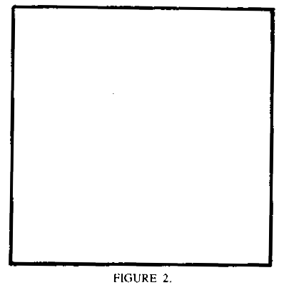
This draws a square. But it doesn't return the turtle to the same heading it started with. Also it only draws one size square and it isn't written so that anything else can be done with the same procedures. With the other SQUARE, you could use the POLY procedure it called to draw triangles, pentagons, octagons, and circles of any size.
What is a "good" approach to drawing a rotating cube? Let's first make some simplifying assumptions. Let's assume that we're looking at the cube from right alongside, so we can't see either the top or bottom faces. Later we can solve this harder case.
How can we do this? Remember some good Logo advice: to solve a hard problem, break it up into sub-problems. What are good subproblems for the drawing of a cube? Well, how about the drawing of one size of the cube! After all, a cube is just six square sides connected to one another.
How do we draw a side of a cube on a two-dimensional display screen? First, we must decide what angle we're looking at the cube from. If we draw it form the front, it's a square, but from the side it's a "squished" square. And if we look at it at just the right angle, it's only a straight line!

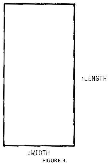
Let's write a program to make a square appear to rotate in space this way. First we need a program to draw the square viewed from any angle. This is just a problem of drawing two rectangles. Here is a rectangle-drawing procedure. It will take two arguments, a length and a width.
TO RECT :LENGTH :WIDTH
   FD :LENGTH
   RT 90
   FD :WIDTH
   RT 90
   FD :LENGTH
   RT 90
   FD :LENGTH
   RT 90
END
 Now we will set up the rotation. We will first make the important
assumption that we want the square to rotate at constant speed.
We will make the square 100 turtle units along each side when viewed
head-on.
TO ROTATESQUARE
   ROTATESQUAREREC 100
END

TO ROTATESQUAREREC :LEN
   CLEARSCREEN
   DRAWSQUARE :LEN
   ROTATESQUAREREC (:LEN - 1)
END

TO DRAWSQUARE :WIDTH
   RECT 100 :WIDTH
END
The program will start by drawing a square head-on. Then it will start to draw figures in which the width is one turtle unit less each time, so the square will appear to "shrink". Finally there will come a point when the original square shrinks to a straight line. What happens next?
What happens is that it starts to do everything it's done once again, but this time in reverse order! Surprising? What we're doing is now calling DRAWSQUARE with a width that is a negative number. Negative "widths" just mean negative arguments to FD commands. Negative arguments to FD mean moving backwards instead of forwards that same distance--the dimensions of the drawn rectangle are still the same. Therefore, everything works out all right.
But now what happens when the width of the square finally gets back to 100 (that is, the argument to ROTATESQUAREREC is -100)? It keeps right on increasing in length beyond 100! But that doesn't make any sense--the square measures only 100 units along each side, so there's no way at all a dimension can ever seem larger.
In summary, this program appears to work pretty well, then gets into trouble when it reaches a certain point. What we'd like it to do at that point is something different. So let's add a check for this situation. then we can call a routine just like ROTATESQUAREREC, but one that also increases the angle each time.
TO ROTATESQUARE
   ROTATESQUAREREC1 100
END

TO ROTATESQUAREREC1 :LEN
   CLEARSCREEN
   DRAWSQUARE :LEN
   IF (:LEN = -100) ROTATELINEREC2 :LEN
   ROTATELINEREC1 (:LEN -1)
END

TO ROTATELINEREC2  :LEN
   DRAWSQUARE :LEN
   IF (:LEN = 100) ROTATELINEREC1 :LEN
   ROTATELINEREC2 (:LEN + 1)
END
Let's run this program. How does it look? Well, for one thing, it seems to "jerk" whenever it reaches its maximum width; that is, whenever we start calling ROTATESQUAREREC2 instead of ROTATESQUAREREC1 or vice versa. To understand this, obtain something shaped like a square and stare at it as you rotate it in front of you. You'll notice something interesting: the width change is slow when the width is large, and fast when the width is small. And the width change of the cube slows down gradually as the cube is viewed more head-on, until finally it stops increasing entirely. Then it slowly starts to decrease, in just the reverse of the previous operation. So the change in the width really can't be modeled very well by just adding 1 turtle unit or subtracting 1 turtle unit from the previous width. Instead, the width change speeds up and slows down periodically.
So how do we model this sort of behavior? That seems difficult, and it is. So mathematicians have come up with a way of giving us the solution so we don't have to rediscover it every time we need it. It's called the cosine function. In LOGO COS takes one argument. The value of COS :X is proportional to the width of a square viewed at an angle of X degrees from head-one. So COS 0 is proportional to 100 turtle units. COS 45 is proportional to the width when halfway turned (that is, about 70 turtle units), and COS 90 is proportional to the width when viewed sideways (that is, 0 turtle units).
Notice I say "proportional". This means we have to multiply by some fixed number in order to get the exact width we want. Mathematicians have agreed to always scale their cosine function between -1 and +1, so the LOGO function COS, following this convention, never gets larger than +1 nor smaller than -1. (This is because mathematicians don't know how big your square is!) Well, we want our width to never get larger than +100 nor smaller than -100. So the expression we can use for the apparent width of our rotating square is 100 * (COS :X).
Here's the improved program, using the cosine function:

TO ROTATESQUARE
   ROTATESQUAREREC 0
END

TO ROTATESQUAREREC :ANG
   CLEARSCREEN
   DRAWSQUARE (100 * (COS :ANG))
   ROTATESQUAREREC (:ANG + 1)
END

This is a lot less messy program. It makes the rotation look a lot better. The cosine function does most of the work.
Notice I've renamed the argument to ROTATESQUAREREC. Wonder why? Notice that this really is like the viewing angle from which we see the square. Each time we draw a new square we increase this "angle" by the same amount, so this represents the constant rate of rotation which we have assumed for the square. In fact, this can be show to be another meaning of the cosine function. Consider the following situation:
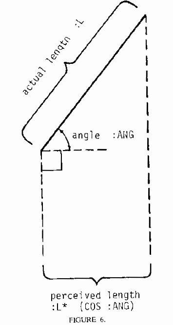
The "cosine" function, as we are using it in this situation, is really the ration of two sides of a right triangle. This is the more traditional way of defining the cosine function.
Write a program to model a "waving hand", avoiding the jerk bug:

Let's once again look at the behavior of this program. It's rotating all right now, but notice that the left side of the rectangle (assuming you're always starting the program with a heading of 0) is always drawn in the same place on the screen. This is not true of the other sides of the rectangle:
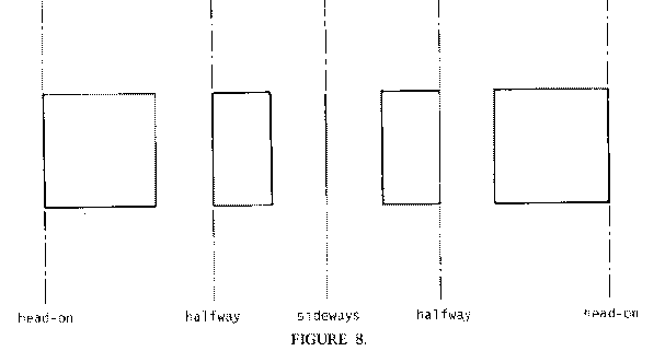
This fact that one of the sides acts as if it were fixed in place may be a limitation we will want to overcome in getting a cube to rotate. Remember a cube has six sides and twelve edges, so even if we assume one edge is remaining still while the cube rotates, we've got lots of other edges to worry about! But notice that we can already draw some interesting rotating shapes. Consider what happens when the following shape rotates about its central axis (assume the squares are transparent).
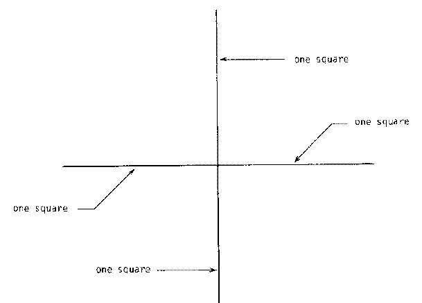
We can think of this as a program with a fancier sort of DRAWSQUARE--instead of drawing a rectangle, it should draw four rectangles, each at a different "angle", superimposed on one another. So all we need is this:
TO ROTATE2
   ROTATE2REC 0
END

TO ROTATE2REC :ANG
   CLEARSCREEN
   DRAW2 :ANG
   ROTATE2REC (:ANG + 1)
END

TO DRAW2 :ANG
   RECT 100 (100 * COS :ANG)
   RECT 100 (100 * COS (:ANG + 90))
   RECT 100 (100 * COS (:ANG + 180))
   RECT 100 (100 * COS (:ANG + 270))
END
Write and try out a program to give the impression of the following object in rotation, as viewed from the side. The object consists of an equilateral triangle, a square, and a regular hexagon, each with sides of length 100 turtle units. The three objects are connected along a single side. The plane of any of the shapes forms 120 degree angles with any of the other planes.
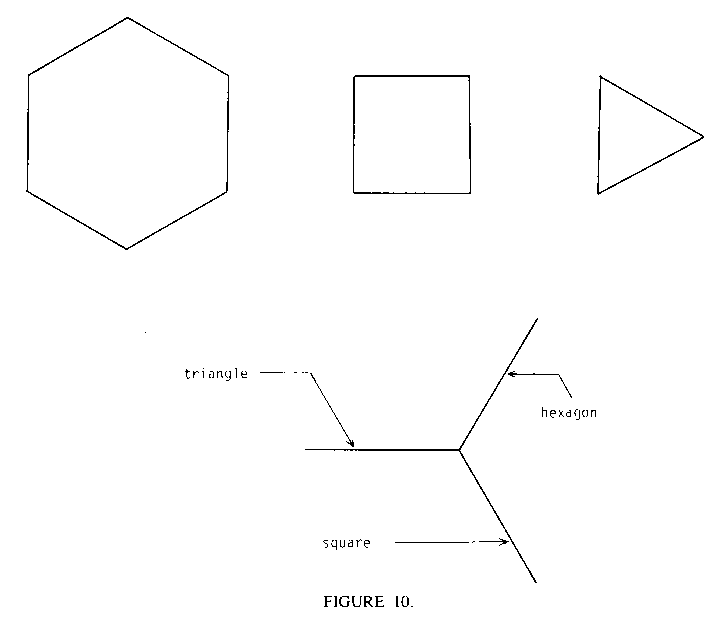
Let's get back to this cube problem. Rather than trying to figure out in general how to rotate a square about any line, maybe we ought to work our way up to this. Consider a square rotating about a line through its center--that is, the line through its center at rest and everything else moving. Sound hard to program? Well, take heart, because this really isn't that much different from what we did previously. As far as width change, the two rotations are the same! It's just that in the earlier case the center of the drawn rectangle is moving; in this case it's fixed. Thus, in one sense this case is simpler.
But in another sense it's not. Our way of drawing the rectangle (which in turn represents the rotating square) was to start from the lower left corner. That's a rather strange place to start. After all, it might seem more natural to think of a drawn square in terms of the position of its center. When you talk about the "position" of some object, you usually are referring to the middle of that object, not one of its corners.
So one way out of this problem might be to write a new rectangle-drawing program that works in terms of the center of the object you're drawing. You leave the turtle in some place, call this procedure, and it assumes the place where the turtle is should be the center of the drawn rectangle. How can we make a modified RECT to do this? Well, all we have to do is add some special instructions at the beginning and end of the program. In the beginning we'll need to handle moving from the center to the lower left corner; and then, when the program is finished we'll need to return the turtle from the lower left corner to the center. (And note the same code that gets us from the center to the corner can be used to get us back again, so we can write a procedure for that.)
TO CENTERRECT :LENGTH :WIDTH CENTERCORNER :LENGTH :WIDTH RT 180 RECT :LENGTH :WIDTH RT 180 CENTERCORNER :LENGTH :WIDTH ENDNow let's use this program to make the square appear to rotate around a vertical line drawn in the plane of the square and through its center.
TO CENTERCORNER :LENGTH :WIDTH PU LT 90 FD (:WIDTH/2) LT 90 FD (:LENGTH/2) PD END
TO CENTERROTATE
   CENTERROTATEREC 0
END

TO CENTERROTATEREC :ANG
   CLEARSCREEN
   DRAWCENTERRECT (100 * (COS :ANG))
   CENTERROTATEREC (:ANG + 1)
END

TO DRAWCENTERRECT :WIDTH
   CENTERRECT 100 :WIDTH
END
Write and try out a program to rotate a circle in space, like this:

That is, simulate what happens to the Greenwich and International Date Line great circle as you view the spinning earth from a point opposite the equator.
CENTERROTATE works fine. But some problems still lie ahead of us on the road to rotating cubes. Consider the view of the rotating cube from the top:
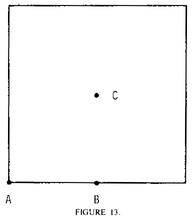
Where shall we choose the center of rotation to make things easiest? Well, axis A won't be too good; we'll have to treat two of the sides as different from the other two. Axis B is an even worse prospect, for the same reasons.
But what about axis C? That seems a logical place, being in the center of everything. So let's choose it. The only problem is that now we'll have to solve a more general rotation problem, that of rotating a square about an axis not in its plane.
Sound tricky? Perhaps. But remember one thing: the change in the apparent width of the square as a function of time should be exactly the same. This is true since the only thing that affects the apparent width is the angle between the viewer and the plane of the square. Since the cube is always rotating at a constant rate, this angle is always changing at a constant rate, and hence the width change always looks the same, irrespective of the position of the axis of rotation.
What the axis of rotation does control, however, is the relative position of the rectangle as a function of time. You can see this by the difference between our side-as-axis and center-as-axis rotation programs. In the first, one of the sides stays still and the center of the rectangle moves back and forth; in the second, both the sides move back and forth, but the center remains fixed.
So find yourself a cube. Hold it between the centers of two opposite sides, look at it from the side, and rotate it. See what happens to the center of any given side? It travels back and forth, symmetrically in front of the center of rotation.
Now notice some funny things about this rotation of the rectangle's center. It moves fastest when it's near the center of he path, and slowest coming eventually to a stop, and then reversing its motion when it's near the left and right extremes of its motion. To illustrate (the view from the side):
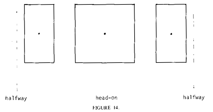
What does that remind you of? Remember the original situation in which we decided to use COS, the cosine function? That was when we were trying to get the width to change the right way. Well, this new discovery of ours seems to be saying that we can do exactly the same thing to control the position of the center of the rectangle! That is, assuming we call the vertical line running through the center of the display screen (the "y-axis") the axis of rotation, the center of the rectangle should be something proportional to COS :ANG to the right of this axis (remember COS can also be negative, meaning to the left of the axis), where COS :ANG is also the width of the rectangle.
The only question is what should be the proportionality factor on this center location to COS :ANG? Well, look at the previous diagram again. If the cube is 100 turtle units along each edge, this means that the axis of the center of rotation of that cube must lie 50 turtle units away from the center of each side square (or, more properly, from the axis through the center of each side square). So the expression we should use is (50 = (COS :ANG)).
So here's our new program for rotating a single side of a cube.
TO ROTATESQUARE3
   ROTATESQ3 0
END

TO ROTATESQ3 :ANG
   CLEARSCREEN
   DRAWSQUARE3 (100 * (COS :ANG))(50 * (COS :ANG))
   ROTATESQ3 (:ANG + 1)
END

TO DRAWSQUARE3 :WIDTH :CENTERPOSITION
   PU
   HOME
   RT 90
   FD :CENTERPOSITON
   LT 90
   PD
   CENTERRECT 100 :WIDTH
END
Watching this program now, one feels a sense of unease. It's working pretty well, but there's something funny about its behavior. Study what goes on:
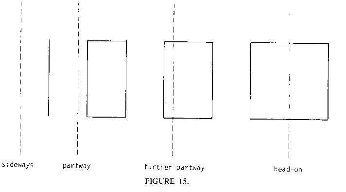
It seems to move back and forth too much. Get out a real cube and compare it to what you see here. Notice that the square is doing all the right things--its width and center position are changing. But these things are not happening at the right time. The width of the square is largest when its center is farthest to the right or left, and the width is smallest (that is, the rectangle is a straight line) when the center is right in the middle of the screen. This is just the opposite of what happens when a real square face of a cube moves; when it's head-on and centered on the middle of the screen, its width is widest.
This is a good example of what is called a nonlinear bug--everything works OK by itself, but when we put it all together we discover some problems in the way the pieces relate to each other. The particular nonlinear bug in this case has to do with phase, so I call it the phase bug. Phase is important in many things having to do with engineering. The word refers to the relative timing of several repeated actions with respect to one another. An example is an audio system in which you are driving two different speakers; if the timing is off between the signals supplied to the speakers, you can get funny effects, and the speakers are said to be "out of phase".
A similar situation is present with this square. The width change is out of phase with the center position change. How do we fix it? We have to get the width "ahead" of the center position. How much ahead? We want the width maximum to occur when the center is all the way to the right, not when the center is in the middle of the screen. That's a quarter of the whole trip the center makes, which implies a change in the angle argument to COS of 90 degrees. So all we have to do is to change the argument to the COS, where it is used to determine the center position. It must be 90 degrees larger.
TO ROTATESQUARE4
   ROTATESQ4 0
END

TO ROTATESQ4 :ANG
   CLEARSCREEN
   DRAWSQUARE3 (100 * (COS :ANG))(50 * (COS(:ANG + 90)))
   ROTATESQ4 (:ANG + 1)
END
Now we only need to generalize this program to handle four sides at once, and we should have our rotating cube. Since we can get any given side of the cube to do its thing, we should simply throw in four calls to DRAWSQUARE4 in ROTATESQ4, just as we did earlier with our ROTATE2 program. (Assume that the cube is transparent, so you can always see all the edges.) But note that the four sides have different phases with respect to one another; since they are at right angles to one another, this means the angle arguments should be 90 degrees apart, just as in ROTATE2. Finally, we have:
TO ROTATECUBE
   ROTCUBE 0
END

TO ROTCUBE :ANG
   CLEARSCREEN
   DRAWSQUARE3(100 * (COS :ANG))(50 * (COS(:ANG + 90)))
   DRAWSQUARE3(100 * (COS(:ANG + 90)))(50 * (COS(:ANG + 180)))
   DRAWSQUARE3(100 * (COS(:ANG + 180)))(50 * (COS(:ANG + 270)))
   DRAWSQUARE3(100 * (COS(:ANG + 270)))(50 * (COS(:ANG + 360)))
   ROTCUBE (:ANG + 1)
END
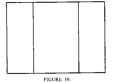 It works!
There are many interesting related projects that you can try. Try to anticipate exploding, jerk, and phase bugs.
a. Generalize this program to allow the rotating cube to be viewed from any angle. Sound hard? Not really. This probably requires a different approach from the one described previously. It would probably be easier to try to do this by figuring out what happens to the corners of the cube, rather than the sides. Then, once you know where the corners go, draw lines between them as the sides (Hint: try first solving the problem of getting a point to rotate in a circle.)
b. Write a program to rotate a tetrahedron in space (the thing with four equilateral triangles as sides).
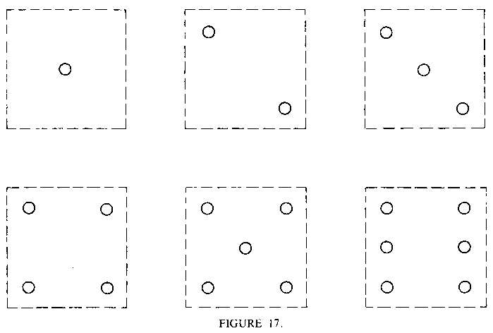
c. Modify the cube rotating program for (a) so that you can identify the sides. This probably means putting some sort of special marking on them. However, this means you will have to figure out what the marking looks like from an arbitrary viewing angle, so you probably won't want to make it too complicated. For example, you could use the code used on the sides of dice:
 d. Use the program for (c) to write a program that simulates the tossing of
a die. (This would be good to use with other computer games.) In other
words, when you do a "toss" the cube rotates at a random uneven speed
in a random direction on the screen. Finally it slows down and comes to
rest with one random side facing the front.
e. Use the program for (a) to develop a game in which you display on the screen a "cockpit view" of "flying over" a cube at a constant air speed. Perhaps the object of the game might be to release a bomb at the right time so as to have it "blow up" the "German submarine" hiding under the cube. (For non-militarists, maybe dropping the basketball into the hoop.)
f. Generalize the idea of (e) to create a three-dimensional spacewar game. Perhaps this could involve trying to maneuver around a cube representing the "enemy ship" while trying to avoid falling into the sum. Or have two people at two different consoles compete against one another, each viewing the other's ship as a cube.
g. Use the program of part (a) to rotate scenes containing several cubes together.
h. Use the program in (g) to write a conversational program that allows the user to specify how to build a certain object from cubes. The program then builds it for him and allows him to view it from all angles.
i. Write a program to rotate a solid cube--that is, one you can't see through. this means that some parts of the lines on the "back" of the cube will have to be omitted. This program can then be used to improve some of the other programs mentioned previously involving cubes.
j. Write a program which uses the circle rotating from section 11 to simulate a ball rolling across the Screen. You would probably have to draw some circles on the sphere in order to give a good impression of its "sphericalness", perhaps like this:
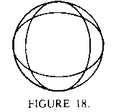 k. Use the program of part (j) to make an even more realistic bouncing
ball program, by including rotation of the ball in the total effect.
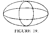
l. Modify the program of part (j) to model a spinning "football" (hint: a football can be approximated as a squashed sphere:
m. Improve any of the programs above by introducing perspective effects--that is, the effect of something getting smaller the farther away it gets. Use the notion of "vanishing points".