We are experiencing the dawn of an era where small
computers in the form of cellular telephone devices and personal digital
assistants (PDAs) are dominating the market and invading our lives. Laptop
computers and notebooks�the truly personal computers�are increasingly reduced
in size, while becoming more powerful at the same time, making the promise of
information mobility a reality. Today, the most commonly used mobile computer
is the "smart phone", an integration of cellular phones and PDAs.
Other devices, such as wearable computers with head-mounted displays, are also
becoming popular and we will probably see more of them in the near future.
Devices that support mobility have some common
characteristics as a consequence of their small size and their support for
connectivity. Among the most prominent characteristics are the following:
�
Limited processing power, memory and storage capabilities.
�
Small screens with fewer pixels and a smaller set of colors than
the traditional computer displays.
�
Unstable wireless connectivity, which provides a smaller
bandwidth with great fluctuations.
�
Limited input capabilities, with slow, difficult and error-prone
methods.
Despite their limitations, mobile devices are becoming
increasingly popular. We expect that near-future technological advances will
overcome most of the above limitations, except for the small size of the screen
(Kasik, 2004). Due to the desired small size and weight of mobile devices, the inherited small screens will probably continue, although we expect the screens to be enriched with more pixels and more colors.
The mobility and portability of these devices make them
good for accessing digital content in remote places, where a standard computer
is unavailable. Today, it is possible to browse the Internet through wireless,
handheld devices and even make transactions such as purchases over the Web.
Although these actions can be performed from a desktop computer faster and with
more security, people find this technology useful because it permits them to
operate while being away from their office. Moreover, many companies support
their employees using mobile devices and, in some cases, they also provide them
with the hardware.
Among the people needing remote access to information, we
can identify a group of technical people that need to consult drawings and
diagrams while working away from their office. Examples of such cases span from
technical managers visiting construction sites, to extreme situations where
technicians may be hanging from towers in order to install or maintain isolated
equipment. The working environment, with occasionally harsh conditions and the
distance from the supporting office on one end and the need to consult several
diagrams repeatedly on the other end, suggests that a mobile device capable of
presenting those diagrams is highly desirable. The fact that companies nowadays
have so many diagrams in digital form makes the mobile, handheld devices almost
ideal for this task, provided that the problems of presenting diagrammatic information
in small-screen devices are solved.
Presenting electrical diagrams�created for presentation
on large sheets of paper�into small-screen mobile devices is a challenge.
Simply shrinking the image is not effective: small screens do not have enough
pixels to handle large images, and even if they did, the image would become so
small that it would be unintelligible. Moreover, the
transmission of large images over the limited and highly fluctuating bandwidth
of wireless links would make sending the full image problematic. Therefore, we
need a solution that presents to the users the most content their devices can
handle, taking into consideration the small screen and the limited networking
and processing resources of those devices. This thesis proposes a computer
program design that addresses these problems.
This thesis will discuss the difficulties of partitioning
diagrammatic content of a technical nature and presenting it on small-screen
wireless devices. The specific application investigated is to create a design
for a program that will present electrical diagrams created for presentation on
large-size paper documents on small-screen mobile devices, to facilitate
maintenance tasks. This design includes provision for dynamic on-demand presentation
that meets the needs of the users and the capabilities of their devices at
every request. A computer is capable of constructing complex diagrams fast,
given the appropriate directions.
Our work attempts to explore novel ways to infer the
semantics of electrical diagrams automatically, construct internal
representations, and then present the content to the users in coherent units.
The major issues addressed in this process are the intelligent ways of
partitioning the drawing images to formulate coherent units of information for
the user and efficient ways of drawing parts of the technical diagram on a
small screen. User-interface and navigation issues will be considered also.
Although the focus of this thesis will be on electrical
diagrams only, many of the techniques and strategies discussed in our study
will be suited to display other types of technical diagrams as well.
The idea for this work came from the observation made by
Boeing (Kasik, 2004) that, for every job, a technician made an average of thirty interruptions to consult drawings. Therefore, a computer program that could intelligently and meaningfully present those technical drawings in a portable, small-screen device through a wireless link would dramatically reduce the problem of time spent on interruptions.
One might assume that it is easy for technicians to have
the actual paper drawing beside them during their work, but this is not always
practical. Two examples illustrate situations where such a computer program
could be useful because paper drawings cannot be used.
Example 1
Gas turbines are machines that use an extensive network
of sensors to function properly. These sensors are attached on the exterior of
the gas turbine, which is usually located inside a casing. Any technician who
needs to maintain one of those sensors will have to work inside this casing,
sometimes in a very confined space and at a very uncomfortable posture.
Clearly, this is not a place where there is room to spread a big paper drawing.
There are many places on ships where technicians have to work in confined or
hard-to-reach places.
When technicians work in pairs�one working in the
confined space and the other close-by, verbally explaining what the diagram
shows�this can be counter-productive, expensive and time-consuming. Another
method that technicians employ is to photocopy the diagrams they intend to use,
making them smaller or cutting the copies in smaller pieces, but this can be
awkward.
Example 2
Photocopy machines cause a lot of frustration when they
are inoperative. When this happens, a technician arrives and tries to fix the
problem. Although the places where photocopy machines are located usually offer
ample space to spread paper drawings, there are too many drawings for the
technician to carry.� A photocopy machine may have one, two or several volumes
of technical drawings, manuals and troubleshooting guides. To be prepared to
deal with every possible failure, one should carry all these to the place where
the machine is. Even worse, technicians who have scheduled the maintenance of
three different models in one day for instance, will have to carry the triple
amount of technical volumes. Finally, if the technicians receive their
scheduling orders on the road through their cellular telephones, they will not
be able to carry all the applicable documentation for every possible breakdown.
This thesis consists of five chapters. In Chapter II we
discuss important concepts related to electrical diagrams, maintenance task,
content repurposing and the devices capabilities. In Chapter III we describe
previous related work on the subject. In Chapter IV we present our design
proposal and finally, in Chapter V we end with a discussion on the conclusions
and the future work on this topic.
����������� THIS PAGE INTENTIONALLY LEFT BLANK
Everyday, people use images and diagrams to communicate
ideas and meanings to each other. "A picture is worth a thousand
words," says the old proverb illustrating that the expressiveness of
pictures�including diagrams�is so powerful that we use it, together with text
or speech, to build mental models of how things are and how they work.
Pictures, images and diagrams are analogical representations of the real world:
the depicted objects, although drawn simplified, are many-to-one mappings from
the real instances (homomorphisms) (Anderson & McCartney, 2003).
In diagrams, and especially in technical drawings, a
homomorphism usually exists in dimensional, positional, or functional analogies
that help the viewer construct, maintain or use a piece of equipment.
Electrical drawings are technical drawings that represent electrical components
and their interconnections (wiring). They are created according to standard
conventions regarding their layout and interpretation and they usually include
textual annotation to facilitate the tasks performed by their users. They do
not require dimensional accuracy. Typical tasks supported by electrical
diagrams are maintenance, faultfinding and repairs, and assembly and
disassembly of equipment.
Electrical diagrams consist mainly of components and
connectors. The components represent the objects of the electrical system and
the connectors represent the wiring that connects these components. Examples of
components include simple electrical components, such as diodes, transistors
and amplifiers and also more complicated components, such as integrated
circuits or even circuit boards. Very often, the connector symbols bear special
marks that add information such as the direction of flow, meeting points,
continuity, protection screening, multiple wiring per connector, or grounding.
Also, we frequently find textual annotation (standalone, in a box, or in a
bubble) that explains key information about the nearby object. Finally, other
special notation may be used for navigational purposes or as reference to more
detailed views of a component. Examples of all of the above elements are shown
in the following figure, in the order they were mentioned.
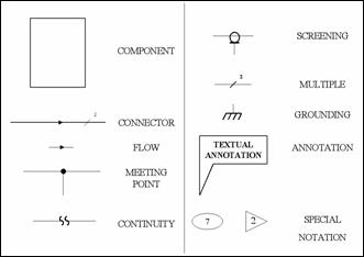
Figure 1.�
Electrical Diagram Example Elements (After (United Technologies Corporation, 1985))
Occasionally a group of components, together with their
interconnections, appears as a separate group enclosed inside a box. The grouping
occurs because of functional similarity or physical-location proximity. We can
see such a group as a component, when we are looking at it with a "black
box" approach, or we can see it as a subsystem, when we are looking at it
with the approach of a "glass box". The black box concept is very
common in engineering: the meaning is that we treat the box as a whole, looking
only at its inputs and outputs, being ignorant about the box's interior
mechanism (Wikipedia, 2004). The glass box concept (or� "white box") permits us to know also how the box works internally. Figure 2 illustrates these concepts.
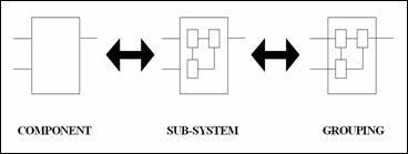
Figure 2.�
The Subsystems Concept
Finally, we may find subsystems that�enclosed inside
boxes�form even bigger subsystems. When this happens, it implies a hierarchical
order between the components.
There are two types of electrical diagrams: wiring and
schematic (Integrated Publishing). Both use vertical and horizontal lines for the connectors and most of the components; in both, the components are drawn simplified. The wiring type includes components that resemble the actual components and denotes their physical location. The schematic type shows components as symbols and emphasizes on the function rather than the resemblance to the components; therefore, it is more useful for maintenance purposes (Ishii, Ito, Iwasaki, Yamamoto, & Kodama, 1981). In our thesis we will be dealing with schematic diagrams mostly, since that type supports maintenance tasks more efficiently. Nevertheless, most of the techniques and strategies we propose are suitable for wiring diagrams also.
For the task of maintenance�including preventive
maintenance, faultfinding and repairs�we need to identify the key operations,
both simple and complex, that technicians perform when they consult electrical
drawings. This task analysis will guide us to what we need to support and will
help us see the problem from the user's point of view. Many of these key
operations are so simple that they sometimes get disregarded (Kasik, 2004).
In a graphic image, a user can infer much information by
purely visual analysis. Key operations related to visual analysis of electrical
diagrams for maintenance purposes are:
�
Identifying an object in the diagram by its name or its function.
Users expect to find objects that "look like an amplifier", for
instance.
�
Identifying an object in the diagram by its physical location.
�
Finding a physical object in the real world by its connectivity
to other objects (wiring).
�
Distinguishing well-connected components from little-connected
components. Sometimes this reveals neuralgic components of the system.
�
Checking for connections between two objects of interest,
possibly through other objects. This is useful for verification hypotheses the
user formulates (e.g. "this must be the cause").
�
Associating textual identification tags (names or codes) with the
components or connectors.
�
Reading textual annotations or hearing them.
�
Zooming in to see more details about a specific entity.
�
Zooming out to include neighboring entities and gain information
on the context of the entity of interest.
�
Tracing a connector to find connected components.
�
Condensing a subsystem into a component or black box.
�
Expanding a subsystem and seeing the interior details (a glass
box).
�
Discriminating between types of entities by making types more
evident. For example, a user might like to see components redrawn in a
different color from the color of connectors and text.
�
Collecting (or grouping) entities of greatest interest for a
specific maintenance job.
Although handheld devices are definitely becoming powerful
assistants, their capabilities are still limited. Watching rich multimedia
content, such as video, with these devices is very challenging (Lyu, Yen, Yau, & Sze, 2003), but so are other common tasks such as browsing the Web (Alam et al., 2003) (Yang & Wang, 2003) (Jones, Marsden, Mohd-Nasir, Boone, & Buchanan, 1999). The reasons that common tasks become difficult for mobile handheld devices are in the devices' inherent limitations on processing power; screen size; network connectivity, and input.
Handheld devices have evolved much, but still their
processing power and memory capacity are limited. Existing device processors
run at various speeds from 8 MHz to 400 MHz (Ferguson, 2002), significantly slower than desktop computers. Some contemporary PDAs are equipped with 128 MB of RAM, while inexpensive devices have only tens of kilobytes (e.g. 160 KB total RAM) today, running on special operating systems and interpreters (e.g. KVM) (Motorola).
With the limited processing power of mobile devices,
application developers cannot rely on processing on the client's side. Instead
they are forced to develop "thin clients" where little processing
takes place on the device, and most occurs on a server. This approach typically
uses much bandwidth. For example, instead of shipping simple commands for a
zooming operation, a thin client will need the whole image to be recalculated
on the server and the result transmitted back to the client. Unfortunately, the
small memory does not permit pre-fetching (i.e. downloading) related data to
the client (like images from the adjacent zoom levels), as there is not enough
space to store the data.
A typical PDA's screen has 160 x 160 pixels of resolution
and a cellular phone's screen can be 120 x 80 pixels only (Alam et al., 2003). Compared to the minimum screen resolution (800 x 600) of desktop computers, the PDA's resolution is twenty times lower. However, not only is the resolution lower for the handheld devices, the screen size is also smaller. PDA's screens�typically 3''�are almost five to six times smaller than those of desktop computers (15''-19''); cellular phones have even smaller screens. Finally, color is yet another factor where handheld devices have less capabilities: while some PDAs show 16-bit color variation, some less equipped models can only show black and white images.
Mobile devices have many options for wireless
connectivity: the IEEE (IEEE, 2004) 802.11-related technologies (recently 802.16 has been added too) and the cellular technologies of 2.5G and 3G (3GPP, 2004) are the most prominent. Bluetooth (Bluetooth SIG, 2004) and IrDA (Infrared Data Association, 2004) can also be used, but only for short-distance links (about 10 meters maximum). All these options have similar problems: wireless links suffer from relatively small and widely fluctuating available bandwidth (Wireless Application Protocol Forum, 2001b). Moreover, the transmission of radio signals consumes significant amount of energy that is drawn from the small batteries of the mobile devices, thus shortening their autonomy. Therefore, transmitting less data will benefit both the network and the devices. The minimization of data transmission can be achieved by compression or by pruning information that the device cannot handle (Singh, 2004).
Entering data in desktop computers is easier than for
small handheld devices. The keyboard and mouse, the principal ways to enter
data in desktop computers, have been replaced by touch-screens in PDAs and
limited keypads in cell phones. Entering data in handheld devices is difficult
and error-prone by nature (Buyukkokten, Garcia-Molina, & Paepcke, 2001). Besides, navigation from page to page (or image to image) needs either additional keys or extra space in the already limited screen area for navigational symbols such as arrows. Good design strategies should avoid the need for users to enter data and, at the same time, facilitate them in giving navigational directions, without consuming the already limited display area.
Viewing all these differences from the desktop computers,
in 1997 Ericsson, Motorola, Nokia and Phone.com (formerly Unwired Planet)
created an industry group named the Wireless Application Protocol Forum (Wireless Application Protocol Forum, 2002) to create and promote industry standards specifically tailored for the handheld mobile devices. The WAP standard is based on existing Internet standards such as HTML, XML and TCP/IP.
One of the main features of the WAP protocol is the
micro-browser, a mini-version of a browser that requires less processing power
and memory and it is suited for presentation on small screens. The WAP
micro-browser is capable of presenting content written in Wireless Markup
Language (WML), an XML-derivative markup language that is designed for mobile
devices. In addition to WML, a similar scripting language called WMLScript is
also supported by the WAP micro-browser.
Each mobile device comes equipped with different
capabilities such as processing power, display, and wireless connectivity. With
a plethora of handheld devices and cellular phones available today, there exist
many combinations of various capabilities. Each such combination is called a
profile. Content targeted for devices with a specific profile may not suit
devices with a different profile. In order for content to suit one device, it
must be tailored to that device�s profile.
In addition, it is helpful to have a common language to
express these capabilities across different platforms. Two approaches have
emerged: the Composite Capabilities / Preferences Profile or CC/PP (World Wide Web Consortium, 2000) and the User Agent Profile or UAProf (Wireless Application Protocol Forum, 2001a). CC/PP uses the Resource Description Framework or RDF (World Wide Web Consortium, 2004) to define a high-level framework for the description of the device's capabilities and the user's preferences, without defining the exact language. UAProf extends the CC/PP model to build a WAP-compatible version that standardizes many of the components defined in CC/PP.
A vast amount of Web content that exists today was
created for access from desktop computers. Very often, authors were not aware
of the new handheld devices and of their browsing capabilities and limitations.
Even today most machines that access the Internet are desktop computers.
During the last few years though, things have rapidly
changed. More and more people access the Internet with their mobile devices
through wireless links. According to the Universal Mobile Telecommunications
System (UMTS) Forum, two billion wireless mobile users will exist by the year 2010
(Beaulieu, 2002). Very often though, some transformation must be applied to the content to suit a specific handheld device or, in other words, a device with a specific profile. With all the different profiles existing today, and even more tomorrow, the transformation task becomes a hard problem.
The solution is to automatically transform the original
content to match the specifications and preferences of the requesting device,
which are described with the CC/PP or UAProf standards. This is called content
repurposing as the content remains unchanged (avoiding inconsistent versions
and storage-space problems) and is made to fit the specific requested profile.
Singh (Singh, 2004) describes some of the main topics of interest in the field of content repurposing:
�
Content analysis to aid repurposing
�
Content description schemes and tagging
�
General content repurposing techniques
�
Techniques for maintaining (and expressing) semantic and
syntactic integrity of content
Stated in simple terms, content repurposing is the
ability to automatically prepare and present specially tailored versions of
existing content, while keeping the original form of the content intact in one
always-consistent version.
���������������������������������������
Despite an extensive literature that covers areas related
to diagram understanding and content repurposing, we have not found any
literature dealing with the specific problem we are addressing. In the next
paragraphs we will discuss previous attempts to solve problems similar to ours.
Understanding diagrams, recognizing and interpreting
their semantics, is an active area of research. There are two kinds of
diagram-interpretation methods: on-line and off-line. The off-line methods take
as input scanned (still) images and try to infer semantics mainly from spatial
arrangement only, while on-line systems can utilize temporal information also,
such as timing of strokes for example, making thus recognition easier (Hutton, Cripps, Elliman, & Higgins, 1997).
(Anderson & McCartney, 2003) is an on-line approach that manipulates diagrams directly without interpreting the images into symbolic representations first. As a basis for this direct manipulation, they use the inter-diagrammatic reasoning (IDR) approach, in which a general syntax and a set of operators for diagrams are specified. Their approach is similar to high-level image analysis.
(Ishii et al., 1981) discusses the automatic off-line input of logic-circuit diagrams from scanned pictures. Their algorithm detects signal lines (connectors) and symbols (components) first and then recognizes text. This approach is similar to ours for the off-line recognition and classification, but their design imposes strict drawing conventions. For instance, the drawings must have only template-based symbols and the line branches must all have characteristic dots to denote a branch. To recognize components, they use a pattern recognition algorithm that searches for T-shaped patterns only, while we use many more patterns.
(Watanabe & Nagao, 1998) tries to understand diagrams using clues from the textual and layout information of each diagram. In their work, they use as an example case a pictorial book of flora, a book that includes pictures, diagrams and explanatory text to describe the rich world of plants. They attempt to perform some natural language analysis on the textual annotations that surround the diagrams, and then use this information together with the layout of the diagram in a rule-based system to classify words from the annotation into five predefined categories. The way they combine layout and textual information is interesting, but their approach is not universal, as many diagrams do not depend on textual information for their interpretations (e.g. electrical diagrams).
(Lank, Thorley, & Chen, 2000), (Gross, 1994) and (Hutton et al., 1997) discuss different on-line interpretation approaches for images. (Gross, 1994) in its "cocktail napkin" approach describes a system that performs recognition in two stages. In the first stage, low-level recognition is performed through pattern matching for simple shapes and constructs such as circles, boxes, arrows, and letters. In this stage, the simplicity with which such "glyphs" can be identified and matched to predefined patterns is exploited. Spatial relations between glyphs are also recognized and noted. In the second stage, higher-level recognition is achieved through bottom-up parsing, where special high-level recognizers try to match glyphs with specific spatial configurations each (e.g. a tree recognizer looks for spatial configurations similar to trees). In this work, the user
initiates the recognition and also gives directions on the type of diagram
match.
(Hutton et al., 1997) describes a strategy for on-line interpretation of engineering drawings. They also discuss the difficulties and differences between off-line and on-line interpretation, concluding that the on-line approach gives more information, thus making interpretation an easier task. Their primary focus is to distinguish the outline of the main objects and the annotations in the engineering drawing, as the two categories of lines require different treatment. Their main heuristic for classifying a line as part of an object or annotation is the thickness of the line, which�in the case of an on-line system�they derive from the pen pressure applied by the designer.
(Lank et al., 2000) describes a system for on-line recognition and interpretation of hand-drawn Unified Modeling Language (UML) diagrams. In the paper, they refer to a multi-level view of diagram recognition, which describes seven levels of understanding a diagram, starting from the image acquisition up to the full semantic interpretation. In their design, the first step is to classify pen strokes as parts of text characters or UML glyphs. Their heuristic is based on the mean and standard deviation of stroke lengths. After this classification, the heuristics they use to recognize UML entities (such as classes) are based mainly on the number of strokes and various distance metrics such as the ratio of total stroke length to the perimeter of its bounding box. They refer to on-line techniques that are efficient for recognizing a limited set of glyphs (about four glyphs
per diagram type) with very distinct features. Nevertheless, their work is very
interesting�especially on the heuristics they use for the interpretation.
Finally, (Kasturi et al., 1988) and (Kasturi et al., 1990) discuss a system that generates descriptions of the contents of paper-based (i.e. off-line) graphics. Their algorithm begins with separation of text from graphics with a method that is described in (Fletcher & Kasturi, 1988).� Next, they recognize and separate solid components using erosion and dilation techniques and they detect straight line segments. After that, they attempt to recognize simple shapes by forming loops with the already-found line segments. This technique may work well for distinct and separated entities, like in organization diagrams, but it will probably have trouble with electrical diagrams, where many connectors intersect in right angles without forming any entity (a component, for example).
Grammars that can describe visual or graphical languages
are discussed in many papers. (Ferrucci, Tortora, & Tucci, 1994) describes a technique for the semantic analysis of visual languages such as those describable by non-deterministic finite state automata (FSA). The underlying assumption is that the visual language is specified by a relation grammar where sentences are generated by production rules that interpret symbols and the relations between them. As an example of semantic analysis by their technique, they perform the translation of a non-deterministic FSA into its corresponding regular grammar.
(Helm, Marriott, & Odersky, 1991) introduces some new techniques for building visual-language parsers. According to them, most visual languages use a combination of three basic categories of relationships:
�
Network, where lines connect elements in a diagram, such as in an
electrical circuit.
�
Topological, such as containment, intersection or touch.
�
Geometric, such as relative proximity, orientation or size.
The semantic interpretation of diagrams is performed
through the use of constrained set grammars, which differ from traditional
string grammars in two ways. First, possible relations between symbols include
not only adjacency but other relations such as containment and intersection
also. Second, while in string grammars parsing occurs from left to right, in
constrained set grammars there is no natural order in parsing. A difficulty
with this approach is that non-determinism leads to inefficiency as
backtracking occurs very often. Also, with too-strict constraints, it may be
impossible to parse the language efficiently. Therefore, the suggested strategy
is to arrange the constraints in the production rules in a more efficient way,
but no method is provided.
Other papers describing techniques based on constrained
grammars include (Futrelle & Nikolakis, 1995), (Futrelle, 1992) and (Futrelle & Nikolakis, 1996). Futrelle has conducted a significant amount of research in diagram analysis and understanding: (Futrelle, 1990); (Futrelle, 1999); (Futrelle, Shao, Cieslik, & Grimes, 2003); (Futrelle et al., 1992).
Similar to the concept of grammars describing diagrams is
the concept of ontologies or meta-models for the contents of diagrams. (Obrenovic, Starcevic, & Selic, 2004) presents a meta-model framework for content repurposing of multimedia content. The multimedia meta-model defines various concepts that can be useful for repurposing content. Their work is inspired by the Model-Driven Architecture of the Object Management Group (OMG, 2002).
One of the most important meta-model creators is the
Moving Picture Experts Group (MPEG) (MPEG, 2004) which has produced several multimedia standards including the MPEG-7 and MPEG-21 standards (Burnett, Walle, Hill, Bormans, & Pereira, 2003), two meta-models that describe multimedia content. (Tseng, Lin, & Smith, 2004) used these two meta-models as the base for repurposing video content for delivery to handheld devices.
A significant amount of work has been done towards
automatic summarization of textual content. More recent efforts have focused on
the Web content, since much was originally created for accessing and viewing
through powerful well-connected medium-screen desktop computers.
����������� (Alam et al., 2003) summarizes Web pages, often with a variety of multimedia content, for small display devices such as PDAs and cellular phones. This effort is content repurposing: By summarizing Web pages, Web browsing can be done on smaller screens and more effectively as less data needs to be transmitted and displayed. Their approach classifies Web content in four categories: "text", "link", "image" and "other". For "text" they apply natural language processing (NLP) techniques, while for the rest they use non-NLP techniques. The NLP techniques are based on noun extraction by the use of a special tagger (Brill, 1992); lexical relations are found by the use of Wordnet (Cognitive Science Laboratory at Princeton University, 2004) and score calculation through special calculating formulas. For the residual types of content they create labels based on visual clues such as font size and style. These labels are then utilized to transcode the output. Similar visual clues are used by (Rowe, 2002) to match captions to images.
(Delort, Bouchon-Meunier, & Rifqi, 2003) creates summaries by inferring the context of Web documents from the textual information of other documents linking to them. (Jing & McKeown, 2000) extracts important sentences, reduces them by removing inessential phrases, and finally combines them to form coherent summaries. (Buyukkokten et al., 2001) summarizes Web textual content for handheld devices with five different methods of progressive disclosure; the summarization process operates differently for each presentation method. The methods they use are: "incremental", where the content is revealed in three stages (the first line, the three first lines and then the whole); "all", where no progressive disclosure is performed; "keywords", where first only the keywords are shown, then the first three lines and finally the whole; "summary", where first the most significant sentences are presented and then the whole; and finally "keyword/summary", where the first stage shows the keywords, the second shows the most significant sentences and the third shows the whole.� (Yang & Wang, 2003) summarizes large Web documents using a fractal model; a skeleton is initially created for the summary as the user specifies the compression ratio, and sentences from the original document are chosen according to a collection of text features. (McDonald & Chen, 2002) evaluates sentences for summarization combining five well-known text features: the presence of cue phrases (e.g. "in summary"); the existence of proper nouns like names and places; the "term frequency / inverse document frequency" (TF/IDF) metric; the position of a sentence in a paragraph (e.g. at the beginning); and finally, the length of the sentence. Many criteria used for sentence selection and evaluation are based on the work by (Luhn, 1958), (Edmundson, 1969) and (Salton & Buckley, 1988).
Research has also been done on classification of images
for summarization. (Lim, Li, Mulhem, & Tan, 2003) proposes a framework for automatic organization of image libraries. Their method for summarizing images is based on selecting key photos from a collection according to the time stamp and the content of each. (Hu & Bagga, 2004) performed a study on automatic classification of images found in Web pages into seven predefined categories. Their work focused on repurposing Web content for wireless devices, since a categorization of images would be useful for setting priorities for transmission to devices with limited bandwidth for instance. The heuristics they used for this classification are based on features, such as size, irregular aspect ratios, frequency domain features, color domain features, and text features.
Abstraction, like summarization, concentrates information
by hiding the lower-level data and presenting only the higher-level
representations. (Egyed, 2002) proposes an abstraction technique for class diagrams in UML. His approach is based on a rule-based system with rules that cover the limited set of relationships in UML. He also discusses the scaling of the abstraction process, proposing methods for serialization of the process and for resolving ambiguities. The gist of his abstraction method is to identify patterns of components that can be grouped together to form a single construct that replaces those components. Finding these patterns is the most critical part of this process. Some
general rules that can be very useful in recognizing patterns are mentioned by (Nesbitt & Friedrich, 2002). In their work, they apply the Gestalt principles of organization, named by the Gestalt school of psychology (Russell & Norvig, 2003). These principles can be stated in simple laws, such as the law of similarity which states, "similar things appear to be grouped together" (Nesbitt & Friedrich, 2002). Such rules can be applied to many kinds of diagram for grouping related components together.
The content repurposing process can be described as three
steps (Singh, 2004). The first step is to analyze and understand the content; the second step is to describe the content in flexible ways to facilitate reformatting and repurposing; and the third step is to transform the content to fit the specific circumstances. With proper repurposing, we can reduce many problems of handheld devices. For example, when a mobile device cannot handle well a certain type of content, then the proper strategy for the server is to not send it at all.
The techniques for content repurposing can be classified
into four categories: scaling (down), manual authoring, transducing, and
transforming (Schilit, Trevor, Hilbert, & Koh, 2002; Suh, 2003). Scaling means to make the content smaller to fit a small screen; manual authoring means manually tailoring the content; transducing means automatic conversion� (e.g. from HTML to WML); transforming is the most general case and means content modification to more suitable forms for handheld devices (e.g. removing tables if the device cannot handle them). (Knutsson, Lu, & Mogul, 2002) uses the term transcoding instead of transformation, and describes content modification of video and images by removing information to adapt to the requirements of the screen size and the wireless link of a mobile device (e.g. cropping images or removing frames from a video).
(Ma & Singh, 2003) present a technique for downscaling images while preserving thin lines. Their method works well up to the point where the graphics in the image become crowded. (Pea et al., 2004) describes a system for repurposing digital video interactively. Their system (called DIVER) allows the creation of a personal view of the recorded video content according to the selection and personalization of the user. For example, the recorded content might be a 20-minute video of a whole office at work taken by a surveillance camera, while a specific view might show only the manager of the office as he works and moves from employee to employee. (Lyu et al., 2003) presents a system that interacts with the mobile client and can adapt to the client's lack of resources by degrading the presentation quality of video content.
For repurposing diagrams, (Tan, Ong, & Wong, 1993) presents a heuristic method for automatic layout of diagrams. Their method is tailored to Data Flow Diagrams specifically, but their rules give a more general idea of how layouts in other diagrams can be achieved when repurposing (and possibly repositioning) occurs. (Kasik, 2004) describes methods for presenting as much diagrammatic information for large technical diagrams as possible in small-screen devices, while keeping the key characteristics of the diagrams intact. He also proposes some partitioning patterns for adapting graphic images (mainly technical documents) to small screens.
In this chapter, we will present the architecture of a
system that repurposes the content of electrical diagrams and presents it on
small-screen handheld devices. This system consists of off-line image analysis
and on-line and on-demand adaptation of the content to fit to small-screen
devices.
We will first understand the semantics of the diagram
off-line and will create an internal representation of the outcome. Then, we
will dynamically create on-demand images that present the content, taking into
consideration the basic capabilities of the requesting device. Throughout this,
we prefer deterministic approaches in interpreting the diagrams wherever
possible because thus we avoid efficiency problems and we make the system
simpler.
The following figures present a high-level view of the
architecture.

Figure 3.�
Off-Line Process (High Level View)
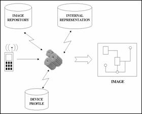
Figure 4.�
On-Line Process (High Level View)
The next sections will discuss first the architecture for
the off-line image analysis, the strategies that we use to adapt the content to
the handheld devices, the issues related to navigation and the user interface,
and finally the needed operations for the client application.
The method we propose for analyzing the image and
interpreting it into a high-level structure implies a layered architecture in
which each layer is a higher-level interpretation of the layer beneath it.
First, we need to obtain the image. Then we need to search this to find
collection of pixels that we can group together as more meaningful entities
such as a line segment, a character or a special symbol. Then we need to search
for higher-level entities such as components and connectors, which constitute
from the already discovered entities. Finally, we need some verification
routine to check for inconsistencies and measure the confidence values for each
interpretation. The layered architecture will provide different results for
each layer. We can imagine layer 0 consisting of an array of pixels, layer 1 bounding
boxes of line segments, layer 2 connected segments (parts of components or
connectors), and so on.
The routine that obtains the image must:
�
Retrieve the image from a database and load it into working
memory.
�
Create an array of zeros and ones (0 and 1) that represents white
and black pixels of the image, respectively.
�
Compute histograms, the number of black pixels per row or per
column of an array (since we expect that the image pixels will be either black
or white, and many more will be white than black).
�
Sort values for subsets of pixels.
�
Compute mean values and standard deviations for subsets of
pixels.
One problem when we try to find line segments in the
image is anomalies caused by scanning faults, drawing faults and other faults,
for instance:
�
Pixels that are extraneous to the edges of a line, like in the
upper edge of the upper connector to the amplifier shown in the following
figure
�
Pixels that are missing from the edge of the line, like in the
lower connector
�
Pixels that are missing and cause disconnection of a line, like
in the lower connector (very close to the triangle).
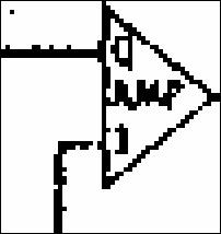
Figure 5.�
Line Segments Anomalies
Even without these anomalies, line segments may have
widths of more than one pixel, making the task of fitting it more complicated.
To manage all these complexities, we propose to find the
average width and height of a line segment and use this to build a bounding box
around it. We will start from a black pixel and search for neighboring black
pixels in all four directions. Every time we fail to find a black pixel in one
direction, we stop searching in this direction and conclude that we have
reached the end for this direction. When all four directions�north, south, west
and east�have been reached to the end, a virtual bounding box will be formed
from the coordinates of the last pixel in each direction.� In addition, the
bounding box for each segment will have a list of connections to other bounding
boxes as it finds them.
If the search starts from a pixel at the periphery of a
line segment, only a small part of the line segment may be discovered instead
of the whole area (see Figure 6 below).
 ��
�� 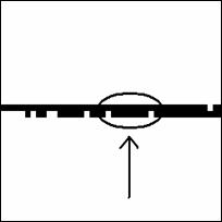
Figure 6.�
Line Segments � Continuity
One solution is to start at a position that will avoid
this problem. Good starting positions should discover black pixels in two
opposite directions (up and down, or left and right). If this does not happen,
then another pixel should be selected as the starting pixel. A second solution
tries to find the longest line segment possible. First, we verify that the
discovered area has a length-to-width ratio of more than 2:1. The method finds
the maximum line segment that can be found starting from any pixel in the
segment. To do this for a horizontal line segment (that is, in a row which has
a large number of black pixels), we use as starting pixels those in the same
Y-coordinate as the original starting pixel. For each of these pixels we find
the furthest point to the left and the furthest point to the right. Then we
take the two points that have the maximum distances for each direction as the
ends of the area.
This method will continue discovering new line segments.�
It will also find pixels that cannot be part of a segment, and will mark them
as bad starting points. When all pixels in the image have been either found to
participate in a segment or marked as a bad starting point, the search for line
segments should finish.
This approach finds line segments in the horizontal and
vertical directions only. This assumption serves well for most segments in an
electrical diagram. The rest of the segments can be found in higher-level
searches.
The method of the previous subsection will miss dashed
lines, sloped lines, curved lines, as well as special markings and characters.
All these entities must be discovered by a subsequent search that finds
connected groups of pixels in the remaining pixels.

Figure 7.�
Finding Remaining Entities
To search for line segments that appear to be connected
together, we can search for bounding boxes that are connected. Bounding boxes
can either "touch" each other or intersect. Having the coordinates of
the bounding boxes makes it easy to check.
Without loss of generality, we may assume that connected
segments are either horizontal or vertical. We can use an indexing scheme that
orders segments according to their orientation and to their starting and ending
coordinates, to find segments that can be possibly connected. Then, we can
verify connections by checking simple rules.
Connected horizontal and vertical segments fall in one of
three categories:
�
Gamma-connection type ( = angle)
�
Tau-connection type (T)
�
Cross-connection type (+)
We can further sub-categorize the gamma-connections and
the tau-connections. Each connection of the gamma type will occupy one of the
four possible corners; each connection of the tau type will occupy one of the
four possible edges. We can enumerate all these connections by counting them
clockwise. The following figure shows all nine connections and their respective
numbering.
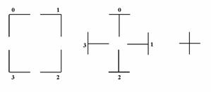
Figure 8.�
Connection Sub-Categories
Each of these three connection types gives information
for higher-level interpretation. For example, a gamma connection can be part of
a component or a turn of direction in a connector. Tau connections will
probably be points of contact between a connector meeting a component. Cross
connections are most probably interpreted as parts of two connectors crossing each
other.
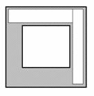
To classify connections, we will use two boxes, OUT and
IN. The width of the IN box will be equal to the width of the OUT box minus two
times the width of the vertical segment; its height will be the height of the
OUT box minus two times the height of the horizontal segment. The idea is that,
if a line segment lies at the periphery, then it will be inside the OUT box,
but outside the IN box. The following figure shows this concept for one
occurrence of each type of connection.
 ��
��  ���
���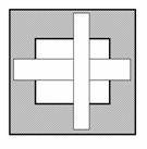
Figure 9.�
Gamma-, Tau- and Cross-Connections
The coordinates for the two boxes are (where width(B)
refers to the width of the vertical line segment�more accurately, to the width
of its bounding box, and height(A) refers to the height of the horizontal line
segment):
|
OUTX1 = min (AX1, BX1)
OUTX2 = max (AX2, BX2)
OUTY1 = min (AY1, BY1)
OUTY2 = max (AY2, BY2)
|
INX1 = OUTX1 � width(B)
INX2 = OUTX2 � width(B)
INY1 = OUTY1 � height(A)
INY2 = OUTY2 � height(A)
|

Figure 10.�
Formation of OUT and IN boxes
Now we check whether INX1<BX1 and BX2<INX2. If so,
then the vertical line (B) is inside the IN box, and we have probably either a
cross-connection or a tau-connection of type 1 or 3 (+, T or  �respectively). If
INY1<AY1 and AY2<INY2, the horizontal line (A) lies inside the IN box, so
we probably have a cross-connection or a tau-connection of type 2 or 4 (+, �|
or |� respectively). If both these checks are true simultaneously, then we have
a cross-connection; if only one of them is true, then we have a tau-connection;
if none of these two checks is true, then we probably have a gamma-connection.
�respectively). If
INY1<AY1 and AY2<INY2, the horizontal line (A) lies inside the IN box, so
we probably have a cross-connection or a tau-connection of type 2 or 4 (+, �|
or |� respectively). If both these checks are true simultaneously, then we have
a cross-connection; if only one of them is true, then we have a tau-connection;
if none of these two checks is true, then we probably have a gamma-connection.
At the end of this procedure, we can codify every
connection according to the identification number, type and sub-type of
connection (e.g. gamma-one), the identification number of the horizontal
segment, and the identification number of the vertical segment.
The next step after finding connected line segments is to
try to identify how these segments form components or connectors. We start by
examining the information that each type of connection can provide us about the
line segments. The cross connection, does not happen too often but usually
occurs between two connectors. It can also happen between one connector and a
boundary line, auxiliary lines that separate groups of electrical components to
denote functional similarity or location proximity. They either form closed
rectangles that include parts of the electrical diagram to group them together
in subsystems, or they separate electrical parts into different locations by
open straight lines. The tau connection usually occurs between a connector and
a component; the connector ends at the edge of a component. Sometimes this
connection can happen between two connectors, usually with a dot at the point
of connection, denoting the meeting. The gamma connection almost always
indicates the connection between two similar entities; it happens between two
line segments of either a connector or a component. The gamma connection can
give us reliable conclusions due to the fact that rectangles are formed by four
line segments that are always connected by gamma connections only. Most
importantly, rectangles can only be components (or annotation boxes in special
cases), not connectors. Even when we visually recognize a rectangle formed by
connectors, it is not really the case. It is true that what we see is visually
a rectangle, but technically it is not.
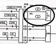
Figure 11.�
Visual Rectangle
An illustrative example will shed some light on this.
Suppose that we consider the pattern annotated by the ellipsis in the above
figure and we recognize it as a rectangle. Visually, this is definitely a
rectangle but, according to the image analysis described earlier, it would not
be interpreted as such. The reason is that, theoretically, a rectangle is
formed by four segments connected with gamma-connections. In the above case we
have instead four tau-connections. In addition, the vertical segments that
participate in these connections extend beyond those connection points. Therefore,
the case described here is merely a set of tau-connections and not
gamma-connections. Subsequently, it does not qualify as a rectangle although,
visually, it seems so. A similar case may appear when we have connectors
crossing other connectors in right angles. Again, patterns will appear that
visually will look like rectangles, but in reality are interpreted as
cross-connected connectors, not as components.
Recognizing a rectangle is simple. Once a gamma
connection has been found, we search clockwise to find the next gamma
connection of the rectangle that shares one of its segments with the former
connection. This process repeats four times until it finds the original
connection again.
Another key step for each identified component is to try
to find tau connections that terminate on the component. This distinguishes
annotation boxes, which are detached and do not have connectors attached to
them. Segments connected to connectors with gamma connections can be recognized
as parts of the same connector (a connector that makes a 90-degree turn). With
methods like these, we can expand knowledge about the semantics of the diagram,
reducing ambiguity. This can continue by following line segments until one of
the following happens:
�
The connector makes a tau connection with an already recognized
component, closing thus the link between two remote components.
�
The connector makes a tau connection with an already recognized
connector.
�
The connector makes a tau connection with an unrecognized
segment, in which case we must wait for that segment to be resolved by other
means (as a form of relaxation).
To identify other entities, such as characters, dashed
lines, special markings and sparse dots, we will begin with the identification
of characters. Several characteristic features facilitate the identification.
First, characters form words and phrases, therefore they tend to appear in
horizontal alignment. Second, the rule in electrical diagrams is that
annotation is done with capital characters using only one font; therefore we
expect to find all characters with the same height. An exception occurs with
some symbols such as "plus" (+) and "minus" (-) symbols,
which denote polarities. We also expect them to have a width-to-height ratio
within certain limits. For example, the letter "I" will have the
minimum ratio, while letter "O" will have the maximum ratio. In
addition, we expect characters to have the same horizontal distance from each
other, meaning the distance between their bounding boxes. The same feature of
proximity applies between lines of text. When multiple lines appear, as it is
common inside annotation boxes, the distance between lines is always the same.
The following figure presents some examples of characters found in electrical
diagrams.
 ���������
Figure 12.�
Examples of Characters
Characters in electrical diagrams also have another
recognizable feature: they tend to appear in standard positions. For instance,
descriptions of components appear in the center of the component. The same applies
with characters inside annotation boxes. Sometimes, characters appear near the
connection point between components and connectors, denoting polarities or
types of connections. Finally, since characters in electrical diagrams appear
consistently in the same font, once we identify a few, we learn their
characteristics that we mentioned above.
Dashed lines almost always appear in vertical and
horizontal directions to represent special connectors or boxes. They are small
collinear line segments; therefore they will have been already identified as
line segments by the process described earlier. These small segments have the
same length and the same amount of whitespace between them, therefore we can
check periodicity by a histogram of the lengths and of the gaps between
segments; a periodic pattern of collinear segment terminations should appear.
Dots are detached little entities, the size of which is
usually smaller than a quarter of a letter's size. We measure size in relative
terms because the absolute number of pixels depends on the scanning resolution
of the original image. Sparse dots can be classified either as participating in
a pattern or as noise; If we cannot classify a dot as part of a pattern, we
consider it to be noise. The pattern would have gaps of same length, as with
dashed lines.
Entities that appear attached to the sides of line
segments are the special markings and small protrusions. These include some of
the most important entities we find in electrical diagrams, such as bullets,
arrows and endings. These entities are always adjacent to connectors and are
either symmetric with respect to the connector, like arrows, or anti-symmetric,
like the lines that cross a connector, denoting multiple wires per connector.
The key for identifying these entities is to find the line segments to which
they are attached. Then, by testing the symmetric and anti-symmetric positions
with respect to the line segment, we can classify these entities as special
markings. A characteristic of these entities is their small length and the
similar size of the two halves on each side of the segment. Their size cannot
be larger than five to ten times the width of the line segment and is usually
close to the size of characters. In the following figure we can see the symmetric
and anti-symmetric parts of three special markings in one line.

Figure 13.�
Examples of Special Markings
Due to the way we identify line segments, small
protrusions on the sides of segments may appear. For example, a small cluster
formed by five pixels in a row may be attached to the segment by its
5-pixel-wide side. Most of these protrusions can be ignored.
After we have found possible components and connectors
with the previous methods, we need to interpret the rest of the line segments,
using more features than just the gamma- and tau- types of connections. Three
features in electrical diagrams are valuable for the task of classifying
segments into components or connectors. The first is that components tend to be
rectangular. This means that some components will have some properties of a
rectangle but will lack one of the required properties. For example, a
component may have four straight-line segments that meet at rounded corners, or
one side of a rectangle may be replaced with a curved line (see Figure below).
From these examples, we can see that it will be helpful to examine structures
that are nearly rectangles and that form a closed shape.

Figure 14.�
Rounded and Curved Rectangles
The second feature is the length of the line segments; in
electrical diagrams, it is common to have long connectors that connect distant
components. Therefore, long line segments are usually parts of connectors; they
rarely are parts of a component. Additionally, it is usual to have a series of
components aligned so the connectors that connect those components are
collinear. Therefore, if we find some line segments that are aligned in a
straight line, and the gaps between them are not empty, it is very likely that
all these segments are connectors.
Finally, a third feature is the presence of special marks
like arrows or bullets on a line segment. Components rarely have any of these
marks on the line segments of which they consist.
While trying to assign line segments to components or
connectors using these features, we may get conflicting evidence. We need to
have a method to rate this evidence to resolve ambiguities. The process we
propose uses a set of probabilistic rules. These rules have an
"if-part" and a concluding part in which one interpretation of the
participating entities is given.
For every probabilistic rule, we find combinations of
entities that conform to the "if-part" of the rule. Each entity gets
one vote for the "then" part of each rule that succeeds for it. After
the voting process has finished, we assign classifications to the entities for
which we have only one kind of votes. Then we continue in the order implied by
the number of votes for each entity. At each step we first check whether the
newly identified entity can reveal the identity of other entities based on the
deterministic rules we have previously discussed in subsection 6 of the current
chapter (identifying components and connections [rule-based]). As an example,
consider the case of a rectangle with a curved line as in the figure above. If
we have just identified it as a component, we may verify that the line segment
that connects to it with a T-type connection is a connector. This conclusion
may trigger more deterministic rule-based identifications, propagating thus the
string of safe conclusions as a form of relaxation.
When the deterministic rule-based identifications cannot
proceed any further, we return to the probabilistic rules and perform some
post-processing pruning on the votes of the remaining entities. More
specifically, for every entity that we have identified through deterministic
rules, we find all the interpretations where this entity participated. Then we
remove the votes from all the entities that were part of combinations that were
incorrectly classified. After that, we test whether the deterministically
identified entities are involved in the "if-part" of any
probabilistic rule and if so, we add more votes to the already existing ones.
Finally, we set the confidence values of the deterministically identified
entities of this round to this of the first entity of this round that triggered
the deterministic identifications.
Here are some example probabilistic rules:
�
If we have a connection of T-type, then the segment that
terminates is a connector and the other segment is part of a component.
�
The above rule applies also for two connectors, for example when
they form a connector branch. Consequently, every combination of entities that
conforms to the "if-part" of one rule will get two votes: one for a
set of connector-component and one for a set of connector-connector.
�
Multiple line segments that are aligned but are not a dashed line
are connectors.
�
Multiple line segments (horizontal, vertical or sloped) that form
a closed curve are a component. By closed curve we mean that, starting from one
segment we find connections through the rest until we end on the one we started
from.
�
The above rule applies also for an annotation box.
�
A closed curve that is detached is an annotation box and not a
component.
�
A closed curve that does not include characters cannot be an
annotation box.
�
A rectangle that does not have at least three line segments or if
it does not have two parallel line segments cannot be an annotation box.
�
Line segments greater than the threshold length of connectors are
connectors. The threshold length is one standard deviation greater than the
average length of a connector.
�
A line segment connected to an entity other than a line segment
or letter is a connector and the other entity is a special marking. Many times
connectors terminate on entities like ground symbols or line-continuity
symbols.
�
A segment (including a boundary line) that meets another line
segment with a cross-connection is a connector.
�
A line segment that has one or more entities attached to its side
(not to its ends) other than line segments (e.g. special markings) is a
connector.
One more issue about annotation boxes is the entity that
they describe. Since annotation boxes are generally formed by parallel lines,
it is safe to infer that the line or lines that point to the entity are those
that are neither parallel to another line nor they form right angles with the
parallel lines. As an example, consider the following figure. Another form of
annotation pointing is a line or arrow drawn from the annotation box to another
entity.

Figure 15.�
Example of Annotation Box
A final point is that some entities may never get
identified properly. This may happen for example if these entities get an equal
number of votes for more than one identity, or the identification they get from
the probabilistic rules may conflict with the deterministic rules that involve
other entities. In such a case, we must consider these entities unidentified.
This will not affect repurposing much as these entities will generally be
enclosed in narrow bounding boxes.
The on-line process of transforming the content and
presenting it on the handheld device's display is a complicated task that
involves many operations. We will attempt to recognize and describe these
operations that will later form the basic modules in our design.
We will begin by describing the desired behavior of the
system and then discuss the general strategy we follow to achieve this
behavior.
Our objective is to build a system that can display the
content of electrical diagrams on small screens, presenting as much information
as possible while preserving the essential details of the diagram. The system
must provide point-of-view controls (panning and zooming operations); it must
also provide operations that permit the contraction and expansion of abstracted
entities (mainly subsystems and textual annotations). In addition, this system
must be able to adapt the presentation of content to the specific capabilities
of the end-user device. Overall, this process of presenting specifically
tailored content is content repurposing.
The purpose of repurposing is two fold. First, it should
reduce the number of bits necessary to represent a screen display. The ideas of
the previous section allow us to create a different, more compact
representation of the same image by transforming a bitmap image to a vector
graphic image and maximize the ratio of visual information to data. Second, it
creates visual representations that are clearer (more crisp and without noise)
and that can be more easily manipulated by resizing and other useful
transformations.
We draw much of our intensity in repurposing electrical
diagrams from the analogies we find in geographical maps. The specialized
content of geographical maps is similar to that of electrical diagrams in many
ways. Maps show cities connected by roads the same way electrical diagrams show
components connected by connectors. Cities and components have different sizes,
and some of them are more important than others. Often roads and connectors
become long as they connect entities (cities and components) in series. (MapQuest, 2004) is well known for presenting geographical location information at different zoom-level maps, a kind of repurposing. As the user zooms out of a map, cities and roads of lesser importance can be hid to remove clutter from the map image. The opposite happens when the user zooms in: more roads and more names appear to give more detailed information. This approach of abstracting entities to remove clutter is used in electrical diagrams modified: components that form a subsystem are replaced by a single
abstract component that represents the subsystem.
The overall strategy we use for diagram presentation is
described in the following paragraphs, followed by more detailed descriptions
in the next subsections.
We start with a pre-defined zoom level and at a
pre-defined location of the original image. This way we start the presentation
consistently each time, helping the user to adjust and get oriented faster. For
the predefined zoom level we need to show a big enough portion of the original
image for the user to get the context, while we want to avoid too much
concentration of content on the user's first contact with the diagram. The
appropriate zoom level should be defined by the complexity of the image. As an
initial level we suggest a window of one ninth (1/9) of the original image. For
the predefined starting location we suggest the upper-left corner, as this is a
standard way to start navigation in a big document.
The location and size of the window determines the components
to be displayed. The components that are included fully in the window should be
displayed; the ones that are totally out of the window should not be displayed.
As for those components that are included partly in the window, the system has
to decide whether to include them in the presentation or not. We will discuss
later how this is determined. We do not need to worry about partially included
connectors. We will always treat partially included connectors in one
consistent way: we will show only the included part until the border of the
window. This way the user will know that the connector continues beyond the
current display. We will see in later subsections how this can be used for
navigational purposes.
For the resolved entities (those that are to be
displayed), we present components and connectors as vector graphics with a
fixed line width (e.g. two pixels). The components' size will be in proportion
to their original size. For example, if the window width at the original image
is 300 pixels and the width of a component is 100 pixels, then the same
component should occupy one third (1/3) of the window width in the device
display. This way we keep the context of the diagram and we avoid confusing the
user. The connectors do not need to maintain proportion in their sizes; they
can get shorter or longer without confusing the user. There is one constraint
about connectors though: the components have to keep their relative positions,
even when connectors reduce their size. For instance, if one component is on
the left of another component, then the relative position of those two
components should be maintained even after shortening the connector that
connects them.
When the border at one side of the window is filled only
with whitespace, that is no components or connectors appear (normal whitespace,
as we explain in the following paragraph), we shift the window towards the
other side to eliminate wasted space. We do this twice: once for the up-down
direction and once for the left-right direction. If both sides in one direction
appear to have whitespace, for instance both up and down, then we chose to move
the window away from the wider whitespace to accommodate as many entities as
possible.
There are two methods for computing whitespace. The first
method computes whitespace taking into account both components and connectors:
when none of these two entities appear, we consider the area as whitespace. We
call this n-whitespace, for normal whitespace. The second method computes the
c-whitespace in which only components matter: if no components appear, we
consider the area as c-whitespace, where "c" stands for
"component-only". The reason for these two different versions is that
sometimes we need to know the normal whitespace, while sometimes we need to
know if any components appear in the area. Therefore, c-whitespace is not
really whitespace; it refers to components only.
When a component is only partially included in the
window, we need to determine whether this component must be displayed or not.
Showing only parts of a component is of little value to the user. A proper
partitioning strategy should anticipate for situations where a component cannot
be presented in full. The option is to shorten the length of a connector so
that the component is fully brought into the available window. If this is not
possible, the component should not be displayed at all. There are two
circumstances where pulling a component inside the window is impossible. First,
when we shorten the connector to its minimum length and still the component is
not fully included. Second, when the component is eventually included fully
inside the window, but it overlaps with another entity. Therefore, we need to
resolve potential overlaps between the new component and other entities in the
window.
When we are presented with a situation where many
components are partially included in the window, we need to choose a component
and apply the appropriate method for bringing it fully into the window. The
easiest approach is to choose the one that needs the smallest movement to
accommodate into the available area. We can determine the length of the
required movement by measuring the distance from the edge of the screen to the
edge of the component, more specifically, the edge that falls outside the
available area. If the chosen component fits into the screen area by shortening
the lengths of some connectors, then there may be room for yet another
component. By using the same method, we can choose another component and try to
accommodate it like the previous one. If the accommodation attempt fails, the
process stops. Also, the process will stop when there are no more components to
choose, which means that all components were successfully accommodated into the
available screen space.
Finally, we must expect that failures may occur during
these complicated zooming, panning and abstracting operations. Consequently, we
must provide an escape route from situations like these. A possible approach is
to attempt to present the immediately higher zoom level and if this fails also,
then present the upper-left corner, just like in the beginning of the
presentation. Alternatively, we could present the immediately previous view,
returning back and allowing the user to request the same or another operation.
If the user selects the same operation and the system fails again, then it
should revert to the original upper-left corner presentation, as with the
previous strategy.
Panning is an operation where the user shifts the
viewable window towards one of usually four or eight predefined directions:
north, east, south, west, or additionally, northeast, northwest, southeast, and
southwest. As the user moves the window new entities may be included and
previously included entities may get outside of the window. Therefore, each
time the window moves, a complete recalculation following the general strategy
must take place.
If during panning we reach at a point where a window has
a lot of c-whitespace on the side opposite to the direction of the movement,
this window should be shifted further towards the panning direction until there
is no more c-whitespace on its border. As an example, consider the case of the
following figure where, due to panning towards the east, we reach at a point
where the western border of the new window is full of c-whitespace. Then, by
shifting the window further to the east, we eliminate the waste and thus we are
able to include more components into the viewable window.
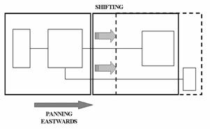
Figure 16.�
Panning Example
According to our general strategy, we start the presentation
at a predefined zoom level. Then the user can zoom-in or zoom-out to see the
content with a different perspective. Essentially, zooming is equivalent to
altering the size of the viewing window. When users zoom in, the viewing window
becomes smaller and the components are displayed larger; the opposite occurs
when they zoom out. To support the two zooming operations it is helpful to have
predefined zoom ratios.
When the user zooms-in, some components that were
originally inside the window may become only partially included. As an example,
consider the situation depicted in the following figure. There is a two-step
process to resolve these partially included components. First, we try to shift
the window towards the component if we find c-whitespace at the opposite
border. Thus we will include more (or all) of that component. If many
components are partially included, we shift the window opposite to the
direction that has the most c-whitespace. Second, we try to bring the component
inside the viewing window by pulling it with the method described in the
general strategy. With this two-step process we attempt to accommodate as many
components in the viewing window as possible.
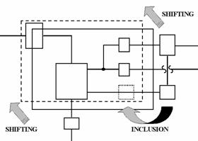
Figure 17.�
Zooming Example
When the user zooms-out, we first test whether
n-whitespace exists. If so, we shift the window to eliminate wasted space.
Then, if we find partially included components, we try to pull them inside the
window area, if possible. Decreasing the size of the image (zooming-out) and
including more components into the viewing window may produce cluttered images
where the shown entities appear too close to be distinguishable. For this
reason, we need a method to decide whether an image is considered cluttered or
not. Some basic rules may well serve this purpose. Identifying and resolving
clutter is discussed in subsection 6 (Clutter Identification and Avoidance).
There is a limit to the zoom level a user can request.
The possible zoom levels span from displaying the component in its original
size (1:1), to displaying the diagram until cluttering occurs. Therefore, there
is no precise limit in the high-level view zoom.
Showing more diagrammatic information in small screens
depends, among other factors, on the ability to concentrate information. There
are several techniques we can use to present fewer, but most significant
content. This is useful for situations where we have a lot of information to
show in a small screen device. Four of these techniques are named below and
then described in the following paragraphs.
�
Detail elimination
�
Abstraction
�
Topological modification
�
Replacement of content with symbols or pointers.
Detail elimination removes
insignificant components from the display. Most components in electrical
diagrams are significant, but possible exceptions are components connected with
dashed lines and annotations.
Abstraction replaces many related
functional units with one functional unit. We discussed the abstraction process
in chapter II, at the description of the subsystem concept. As an example, we
may consider components enclosed inside boundary lines.
Topological modification is
shortening the connectors and presenting components closer together, while in
the original diagram these components might be far apart, as discussed earlier.
Replacement of content with links (symbols or pointers)
is a general technique that can be used to expand non-critical pieces of
information when needed. One example is to insert a special mark whenever a
subsystem is condensed to signal the existence of a more detailed view. This
mark can be interactive in the sense that the user may select it to expand the
subsystem.
This can also be done for textual
annotations that often accompany components and connectors. Those annotations
need not be presented every time a user looks at a diagram. Once they have been
read, users tend to remember the information without looking at them again, so
they can be represented by symbols on the main display. It should be noted that
this refers more to annotations that are long, such as directions or
explanations and less to annotations that are short and give specific data,
such as polarities. Therefore, annotations are an easy target for
concentration, as they can be replaced by special marks that indicate the presence
of an annotation, without displaying the text.
Every useful image should obey some basic rules about
image clarity and clutter avoidance. For example, a rule about line visibility
may say that any line should have a minimum width of two pixels. A rule about
clutter avoidance may say there must be a minimum distance of at least five
pixels between entities to keep the image intelligible. A set of rules like
these should have an order of priority, depending on their importance.
When the produced image becomes cluttered due to the
decreasing process (zooming out), a set of special techniques should be
employed to recover from the situation. Such techniques include replacing
components with their subsystem equivalents (abstraction) or decreasing the
size of all components by a factor greater than the zoom factor. Probably the
best strategy is to reduce the size of the components up to the point where
cluttering occurs again. This time, clutter would be decided by a different
criterion, such as a rule that would state the minimum size of a component
(e.g. a component should have height and width of at least twenty pixels). When
the size of a component is falling below the minimum standard, no more size
reduction can be done. In this case, the only option is to substitute
lower-level components with their higher-level equivalents, that is, the
subsystems that those components constitute.
These changes must take place in a certain order. For
abstraction, the number of components that form a subsystem and the level in
the subsystem hierarchy implies the order in which these substitutions should
take place. We must therefore condense all subsystems of one level before start
condensing subsystems of the next higher level. To do so, we begin with the
subsystem that has the most components; if many subsystems exist, then we chose
to begin with the one that has its centroid closer to the center of the window.
The main piece of information that we need about a device
for repurposing is its screen dimensions. With this information we can adapt
the content of the diagram to the specific device used by the user. This is
achieved by building a special image that fits exactly on the device's display.
Screen size is also necessary to calculate the minimum size of a component and
to determine whether clutter occurs.
Device color capability is also important. In
color-capable displays, we can employ more techniques for presenting
information. For instance, we can show components in different colors when
these components can be expanded. In monochrome displays, we can insert a
special mark that represents the same concept, instead.
The following example illustrates the additional
potential uses of information about the status of the device. Some devices
sense the lighting conditions to adjust display brightness. When lighting
conditions do not permit colors to be distinguished clearly (e.g. in bright
daylight), the system should revert from the first option of color-coding, to
the second option of special marks.
In this subsection we will describe some of the auxiliary
operations that our system needs to perform. Many of these operations have been
mentioned or described shortly in previous subsections. The auxiliary
operations are listed below:
1.
Operation that finds components and connectors that are totally included
inside the viewing window:
This can be easily determined using the X and Y
coordinates of the components and of the viewing window. We will use the
following notation: the coordinates for the components will have a
"C" as a prefix while the viewing window will have a "W" as
a prefix; the coordinate for the left end will be X1; for the right end it will
be X2; for the top it will be Y1 and for the bottom it will be Y2. For example,
CX1 represents the X coordinate of the left end of a component. A component is
totally included inside the viewing window if and only if
(CX1 WX1 AND CX2
 WX2) AND
(CY1WY1
AND CY2WY2).
WX2) AND
(CY1WY1
AND CY2WY2).
2.
Operation that tests whether a component is included only partially in
the viewing window:
If the component is not totally included, then it may
be only partially included. We can easily check for this case by testing
according to the following rule:
(CX2>WX1 AND CX1<WX2) AND (CY2>WY1 AND
CY1<WY2).
If a component fails the first test (total
inclusion), but passes the second test (total or partial inclusion), then it is
only partially included in the viewing window; otherwise, it is not included at
all.
The same operation can be
used to determine whether a connector is included only partially.
3.
Operation that retrieves the identification number and the rest of the
data for a component that lies outside the viewing window at the hidden end of
a partially included connector:
This operation is basically a search in the database
of the internal representation for the components that a connector connects
together.
4.
Operation that attempts to bring a component inside the viewing window
by "pulling" it (shortening the length of its connector) in the
direction of the connector:
This operation is possible only if the connector can
be shortened in each direction, by at least the same length as the needed
displacement of the component in the same direction. This shortening in the
length of the connectors is allowed, provided that the final length will
conform to the minimum connector length to avoid clutter. Also, the entry
points to the components and the orientation of the connectors is not permitted
to change. As an example, consider the case in the following figure, where a
connector that protrudes from the right side of a component and makes a
right-angle turn towards the south connects to another component. The latter
component needs to be displaced in two directions (north and west) to be
included inside the viewing window. Therefore, we have to shorten the lengths
in both parts of the connector, but we also have to keep the same points of attachment
to the two components.
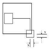
Figure 18.�
"Pulling" a component
5.
Operation that identifies collisions and resolves them:
After bringing a component inside the viewing window,
a collision might occur between this component and the other entities that are
already in the area. This operation first identifies possible collisions and
then resolves them.
For the identification we may use the same operation
that tests for partial inclusion of components. The only needed modification is
that in this case we treat the new component as the viewing window. This way we
test for intersections or collisions of components or connectors. We also need
to extend this test for annotation marks using the same principle.
If we discover a collision
between the new component and another entity, we need to resolve it. If the new
component collides with many entities (more than one), we should abandon the
attempt and reject the new component. If there is a collision with only one
entity, we should try to move the two entities apart in the direction that
resolves the collision the most quickly. We can find this direction by first
computing the collision area and then finding the shorter dimension in the
rectangle that is formed by the collision area. An example is presented in the
following figure. Very often the new component will lie at the border of the
viewing window, therefore it will not be possible to move it outwards, as the
previously described method will indicate. In that case the other colliding
entity will have to be moved inwards. The movement of this entity will be
performed with the same method that brings a component inside the viewing area:
by shortening its connectors in the directions of displacement (and, at the
same time lengthening its connectors in the opposite direction).
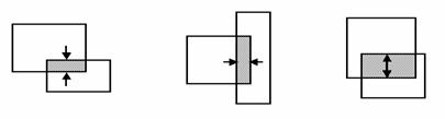
Figure 19.�
Resolving Collisions
Finally, after one of the entities has been relocated
and the collision has been resolved, there is one last test that needs to be
performed. We need to test for possible collisions again, this time with the
relocated entity. If no collisions are found, the process succeeds; otherwise,
we abandon the resolution attempt, we return the old entity to its original
location, if it was moved and we reject the new component ending the process.
6.
Operation that identifies whitespace:
This operation identifies
n-whitespace and c-whitespace on selected areas. More specifically, given the
coordinates of an area, the operation searches within these coordinates for
components (c-whitespace) and other entities (n-whitespace) by their
coordinates.
7.
Operation that constructs the output image and transforms it into
various other formats:
The server must be able to
construct any requested format (by the client) in real time. Due to the nature
of the repurposing application, the native format that the server builds
initially is in a vector-graphics language, such as the scalable vector
graphics (SVG) (World Wide Web Consortium, 2003). Therefore, the server must be able to transform the constructed image from its native format to the format requested by the client. The most prominent options for image formats are SVG, Joint Photographic Experts Group (JPEG, 2004), Graphical Interchange Format (GIF) (TechTarget, 2004) and Portable Network Graphics (PNG) (Roelofs, 2004).
The overall design of the on-line process at the server
is illustrated in the following figure. The depicted cloud includes all the
necessary modules for the on-line part of our proposed system. The main core
includes the general strategy and the basic operations, such as panning and
zooming or condensation and expansion. Other modules that communicate with the
core are the request processor, which prepares the input with the help of the
CC/PP module and the image module; the internal representation interface, which
communicates with the relevant database; the image generator, which generates
the main image of the diagram; the context map generator, which generates the
context map; and finally, the image format transformer, which combines and transforms
the images generated by the previous two modules to the appropriate image
format.

Figure 20.�
Modular Design of the On-Line Process
In this section we will discuss issues related to the
user's orientation, interactivity and navigation and options for panning and
zooming.
We must help users keep orientation and perspective when
they navigate the diagram. For this, we select a typical context-preserving
technique that shows the whole diagram, compacted in a small independent
window. This window, which we call the "context map", will show only
the most important components based on size. The components that are presented
each time in the main window will be highlighted in the context map. This way,
even when topological modifications are performed, the users still maintain
orientation and context.
A user can perform two operations, principally: panning
and zooming. These two operations can be further sub-divided into even simpler
operations, which combine appropriately to provide a complex, but coherent way
of navigation through the diagram. Here, we will summarize these simple
operations in two lists, one for panning and one for zooming.
�
Panning in standard directions: north, west, south, and east.
�
Jumping to components only, skipping whitespace and long
connectors.
�
A special technique in panning is performing topological
modifications, shortening the lengths of connectors to present components
closer to one another.
The various operations of which zooming consists are:
�
Zooming in to show the details of an individual component only.
The most detailed zoom level for a component in vector format occurs when the
component is covering the entire display. The users can request to zoom once
more into the details of the bitmap image that underlies the vector
representation of a component. This way they can visually scan the original
image, if they need to confirm details of the component. This is also a way to
test the system for its credibility, that is, whether or not it performs well
with respect to the interpretations it makes for the components.
�
Zooming out the whole diagram, showing more and smaller
components in proportion.
�
Zooming out while using abstraction, replacing groups of
components with their higher-level substitution units (i.e. subsystems).
�
Zooming out while using detail elimination, removing components
of lesser importance (e.g. those connected with dashed lines).
When zooming out, a combination of these operations must
give a consistent way of presenting the content to the user. As described in
subsection 6 (Clutter Identification and Avoidance), a strategy that combines
these operations to perform the zooming-out operation consistently involves
them one at a time. First the operation that zooms out the whole image is
employed until clutter occurs; then, abstraction is performed replacing groups
of components; finally, detail elimination removes components of lesser
importance.
As a last point, we should mention that in both panning
and zooming we use auxiliary operations, such as determining whitespace,
shifting the window and bringing components inside the viewing window, whenever
possible.
The users have many navigation options: they can pan or
zoom or they can select entities for more specific options. In the following
paragraphs, we summarize these options and suggest ways of making navigation
more effective by giving many options to the user.
The usual way of requesting panning operations is by
selecting appropriate arrows located at the borders of the viewing window.
Apart from the specialized navigation arrows, there are other ways to request
navigation operations. By selecting an entity, the user can request more
complex operations. We will discuss this for three types of entities:
connectors, components and textual annotation marks. We should note that the
selection of an entity could be, by itself, a hard problem due to the limited
ways of interactivity in some devices (e.g. mobile phones).
When the user selects a connector, that could mean to
bring the component at the other end of the connector into the viewing window,
if possible; otherwise move the window to include that component. An
alternative option is, every time the user selects a connector, to present an
instant window box that shows the component at the other end and provides
options such as "move to the component", "zoom-out to include
the component" or "just close the window".
When the user selects a component that represents a
condensed subsystem, it could mean to expand this component to the subsystem
that it represents. When this component includes condensations in multiple
subsystem levels, the expansion should reveal only the next level. An
alternative option is to present an instant window box that again (as in the
connector case) will provide multiple options, such as "zoom",
"expand" or "center the window on this component". If the
user selects a component in the context map window, the option is to center the
viewing window to that component.
When the user selects a textual annotation mark, it
should expand to a box that includes the underlying text. This box should
remain active and visible for a predefined period of time (e.g. thirty seconds)
and then it should condense back to the special mark. If the user selects the
box while it is active, another window may appear providing options, such as
"stay open" or "close".
Another way for the user to interact with the content is
to select two points on the window and thus form a bounding box. Then the user
may select one of the options that the system displays for convenience. It is
interesting that, with this interactivity method, a user can manually select
multiple components and condense them to a subsystem, based on locality. This can
be very useful in situations where the user decides that some components should
not be displayed expanded either because they are of less value for the
maintenance task at hand, or because they form a coherent unit. Some of the
options the system may provide are: "condense", "hide � never
show again", "always show".
Finally, a new approach concerning the way a user
interacts with the content is proposed for devices with only basic input
capabilities: We may use the numeric pad (keys #1 � #9) for navigation, in
combination with different "clicking" patterns for different
purposes. For instance, single click may be used for the image re-centering or
"panning" (key #3 would center on the upper-right corner, for
example); double click may be used for zooming in; continuous pressing could be
used for zooming out.
With all these options, it is likely that a user might
get confused. With proper testing, some of these options will be proved
ineffective, while the potential users might suggest other options as well. A
good strategy to escape this confusion is to start with only a subset of these
options active; then, as time passes and the users become more familiar,
introduce the rest of the options so that the users customize their
environments to their particular needs and preferences. These preferences would
be saved at the client and passed to the server each time the user makes a
request. Users do not need to execute any of these operations, as they are
options provided for convenience and usability improvement, not for resolving
ambiguities in diagram understanding.
In this section we will discuss the required operations
that a client application must perform to be able to participate in this
content repurposing system. To these required operations, we will also include
desired operations that, although not specifically needed, would enhance the
interaction with the server and would make the system more efficient.
We need a client application program that will request
specific diagrams and present the images sent by the server, in response to the
requests, together with all the navigation-aid tools (e.g. arrows). The client
will have to provide the URL of the server for its profile, will have to
support the various image formats and will have to support interactivity based
on the user's selection of entities or areas of interest. It is also desirable
to communicate with the server in an encoded (compressed) scheme that will save
bandwidth and make the transmissions less vulnerable to bandwidth shortages
(vector graphics is one such compressed format). If we want to support these
operations, we need special client software that must provide at least for
image presentation, interactivity and connectivity. It must be robust and light.
One approach is to download the entire electrical diagram
once, in vector graphics format, and store it on the small device. Vector
graphics are intrinsically compressed, so they do not require much space even
for large diagrams. Then the display software would need to do the repurposing
and present the entities within a certain window. A benefit of this approach is
that when users zoom or pan, many of the same entities will remain in the
display window and will not need to be processed much again. Also the network
will be used once for each diagram, only in downloading the vector graphics
format, eliminating the constant need for exchanging information with the
server. The drawback is that this approach requires a significant amount of
processing power and memory on the client. This approach is basically the
opposite of the light client and requires special software for each platform,
making developing and maintenance harder. In our design, we prefer the option
of the light client that depends on the network connectivity with the server.
To compensate for the bandwidth requirement we need special encoding schemes
and compressed image formats.
The biggest problem with respect to the available
bandwidth is the transmission of images. The more compressed the image is
transmitted, the less bandwidth it consumes. Unfortunately, there are a lot of
disadvantages too, when dealing with compressed images. Compression and
decompression are operations that require resources and processing time both in
the client's and in the server's side.
There is one more option we can use for this kind of
application. Since electrical diagrams consist of monochrome, sparsely arranged
graphics of which most are straight line segments, vectors are almost perfect
to describe them. Vector-graphics languages are compact by nature therefore
they need less bandwidth for transmission. On the other hand, the client
application that will present them will need to render them first, which takes
processing time and resources.
There is no easy solution for the client problem, as
there is always a tradeoff between processing power and bandwidth. In this
section we do not provide a design for the client; we merely discuss some
needed operations, the problems that need to be solved and the options we have
for the image format.
THIS PAGE INTENTIONALLY LEFT BLANK
In this thesis, we have attempted to design a system to
understand the semantics of electrical diagrams and construct internal
representations of them in an off-line process. Then an on-line process uses
these representations for real-time repurposing of those electrical diagrams,
adapting the diagram content for presentation on small-screen handheld devices,
taking into consideration the specific profile of each device.
In the off-line part, we have used novel techniques to
parse the diagrams and we have dealt with the recognition and identification of
most of the various constructs found in electrical diagrams of the schematic
type. We have focused on the schematic type since it is more suitable for
maintenance tasks. In the on-line part, we have proposed a general strategy for
adapting the content for small screens, and we have presented methods and
techniques for concentration of diagrammatic information, inspired by the
analogous efforts made previously in the summarization of textual, Web and
multimedia content. We have tried to foresee the difficulties of navigation
through content presented in a small screen and we have included some navigational
aids in our design to help potential users keep knowledge of orientation and
context.
The design we propose is by no means complete. The major
weakness of our work is the lack of results that would evaluate the system we
propose. Consequently, future work should test the validity of the features
that we propose and grade the significance of each feature. A method to do this
is to construct training and testing sets. By machine-learning methods, even
more features may be discovered.
A weakness in the approach we propose for identifying
components and connectors is that it is not very efficient with components that
include sloped or curved lines like triangles or diamonds. This is because
these components do not clearly form tau-connections with their connectors.
Future work may solve this problem.
Also, we have presented the features by which we can
identify characters and dashed lines, but have not provided any specific
method. Recognition of such patterns has been addressed by previous work.
Finding text in images has been discussed in (Fletcher & Kasturi, 1988); for recognizing texture or patterns in images, complicated computer vision techniques have been devised (Russell & Norvig, 2003). Future work must select a method.
In our work we have referred to the internal
representation of the diagram semantics, but we have not specified a detailed
scheme for this representation. We have also not mentioned anything about the
indexing of the database that stores this internal knowledge. We have left
these issues open because we think that many schemes can serve this purpose.
Nevertheless, we have provided the pieces of information that is needed to be
recorded or accessed each time. We believe that XML is well suited for this,
but we feel that an XML-based representation scheme may be a bottleneck in the
performance of the real-time, on-line adaptation process. Future work will have
to try different schemes and evaluate them in terms of clarity and efficiency.
Finally, we presented a set of rules in which every rule
adds one vote for every entity. By evaluating and grading the importance of
these rules, we can assign different weights to each rule and progress to a
more probabilistic scheme. For example, each type of connection can present two
or more hypotheses on the types of the connected line segments. There are
different probabilities for each hypothesis; we can calculate a rough estimate
of these probabilities by examining a fair amount of sample cases where each
type of connection occurs. The task of calculating these probabilities is
subject to future work.
3GPP. (2004). 3GPP Home Page. Retrieved 28 September
2004 from http://www.3gpp.org/
Alam, H., Hartono, R., Kumar, A., Rahman, F., Tarnikova, Y.,
& Wilcox, C. (2003, 3-6 August). Web Page Summarization for Handheld
Devices: A Natural Language Approach. Paper presented at the Proceedings of
the Seventh International Conference on Document Analysis and Recognition
(ICDAR'03), Edinburgh, Scotland.
Anderson, M., & McCartney, R. (2003). Diagram
Processing: Computing with Diagrams. Artificial Intelligence, 145(1-2),
181-226.
Beaulieu, M. (2002). Wireless Internet - Applications and
Architecture. In (pp. 3-3): Addison Wesley.
Bluetooth SIG. (2004). The Official Bluetooth� Wireless Info
Site.
Brill, E. (1992, March 31 - April 03). A Simple
Rule-Based Part of Speech Tagger. Paper presented at the Proceedings of the
Third Conference on Applied Natural Language Processing, Trento, Italy.
Burnett, I., Walle, R. V. d., Hill, K., Bormans, J., &
Pereira, F. (2003). MPEG-21: Goals and Achievements. IEEE Multimedia, 10(4),
60-70.
Buyukkokten, O., Garcia-Molina, H., & Paepcke, A. (2001,
1-5 May). Seeing the Whole in Parts: Text Summarization for Web Browsing on
Handheld Devices. Paper presented at the Proceedings of the Tenth
International Conference on World Wide Web, Hong Kong, Hong Kong.
Cognitive Science Laboratory at Princeton University.
(2004). WordNet. Retrieved 28 September 2004 from http://www.cogsci.princeton.edu/~wn/
Delort, J.-Y., Bouchon-Meunier, B., & Rifqi, M. (2003,
August 26 - 30). Enhanced Web Document Summarization Using Hyperlinks.
Paper presented at the Fourteenth ACM Conference on Hypertext and Hypermedia
(HT), Nottingham, UK.
Edmundson, H. P. (1969). New Methods in Automatic
Extracting. Journal of the ACM (JACM), 16(2), 264-285.
Egyed, A. (2002). Automated Abstraction of Class Diagrams. ACM
Transactions on Software Engineering and Methodology (TOSEM), 11(4),
449-491.
Ferguson, D. (2002). Overcome Device Diversity Challenges.
Retrieved 28 September 2004 from http://www.ftponline.com/wss/2002_11/magazine/columns/wireless/
Ferrucci, F., Tortora, G., & Tucci, M. (1994, 01-04
June). Semantics of visual languages. Paper presented at the Proceedings
of the workshop on Advanced visual interfaces, Bari, Italy.
Fletcher, L. A., & Kasturi, R. (1988). A Robust
Algorithm for Text String Separation from Mixed Text/Graphics Images. IEEE
Transactions on Pattern Analysis and Machine Intelligence, 10(6), 910-918.
Futrelle, R. P. (1990, June 16-21). Strategies for
diagram understanding: generalized equivalence, spatial/object pyramids and
animate vision. Paper presented at the Proceedings of the 10th
International Conference on Pattern Recognition.
Futrelle, R. P. (1992, September 15-18). The Conversion
of Diagrams to Knowledge Bases. Paper presented at the Proceedings of the
IEEE Workshop on Visual Languages.
Futrelle, R. P. (1999, September 13-16). Ambiguity in
visual language theory and its role in diagram parsing. Paper presented at
the Proceedings of the IEEE Symposium on Visual Languages, Tokyo, Japan.
Futrelle, R. P., Kakadiaris, I. A., Alexander, J., Carriero,
C. M., Nikolakis, N., & Futrelle, J. M. (1992). Understanding Diagrams in
Technical Documents. Computer, 25(7), 75-78.
Futrelle, R. P., & Nikolakis, N. (1995, 14 - 15 August).
Efficient Analysis of Complex Diagrams Using Constraint-Based Parsing.
Paper presented at the Third International Conference on Document Analysis and
Recognition (ICDAR), Montreal, Canada.
Futrelle, R. P., & Nikolakis, N. (1996). Diagram
Analysis using Context-based Constraint Grammars, Technical Report NU-CCS-96-01:
College of Computer Science.
Futrelle, R. P., Shao, M., Cieslik, C., & Grimes, A. E.
(2003, August 3-6). Extraction,layout analysis and classification of
diagrams in PDF documents. Paper presented at the Proceedings of the
Seventh International Conference on Document Analysis and Recognition
(ICDAR�03), Edinburgh, Scotland.
Gross, M. D. (1994, 01-04 June). Recognizing and
Interpreting Diagrams in Design. Paper presented at the Proceedings of the
workshop on Advanced visual interfaces (AVI), Bari, Italy.
Helm, R., Marriott, K., & Odersky, M. (1991, April 27 -
May 02). Building Visual Language Parsers. Paper presented at the
Proceedings of the SIGCHI conference on Human factors in computing systems, New
Orleans, Louisiana, United States.
Hu, J., & Bagga, A. (2004). Categorizing Images in Web
Documents. IEEE Multimedia, 11(1), 22-30.
Hutton, G., Cripps, M., Elliman, D. G., & Higgins, C. A.
(1997, 18-20 August). A strategy for on-line interpretation of sketched
engineering drawings. Paper presented at the Proceedings of the Fourth
International Conference on Document Analysis and Recognition.
IEEE. (2004). IEEE Home Page. Retrieved 28 September
2004 from http://www.ieee.org
Infrared Data Association. (2004). IrDA. Retrieved 28
September 2004 from http://www.irda.org/
Integrated Publishing.Types of Electrical Diagrams or
Schematics. Retrieved 13 September 2004 from http://www.tpub.com/content/doe/h1016v1/css/h1016v1_105.htm
Ishii, M., Ito, Y., Iwasaki, M., Yamamoto, M., & Kodama,
S. (1981, June 29 - July 01). Automatic Input and Interactive Editing
Systems of Logic Circuit Diagrams. Paper presented at the Proceedings of
the 18th conference on Design automation, Nashville, Tennessee, United States.
Jing, H., & McKeown, K. R. (2000, April 29 - May 4). Cut
and Paste Text Summarization. Paper presented at the Sixth Applied Natural
Language Conference (ANLP-00) and the First Meeting of the North American
Chapter of the Association for Computational Linguistics (NAACL-00), Seattle,
Washington, USA.
Jones, M., Marsden, G., Mohd-Nasir, N., Boone, K., &
Buchanan, G. (1999, May 11-14). Improving Web Interactions on Small
Displays. Paper presented at the Eighth International World-Wide Web
Conference, Toronto, Canada.
JPEG. (2004). JPEG Home Page. Retrieved 28 September
2004 from http://www.jpeg.org/
Kasik, D. J. (2004). Strategies for Consistent Image
Partitioning. IEEE Multimedia, 11(1), 32-41.
Kasturi, R., Bow, S. T., El-Masri, W., Shah, J., Gattiker,
J. R., & Mokate, U. B. (1990). A system for interpretation of line
drawings. IEEE Transactions on Pattern Analysis and Machine Intelligence, 12(10),
978-992.
Kasturi, R., Bow, S.-T., Gattiker, J., Shah, J., El-Masri,
W., Mokate, U. B., et al. (1988, 14-17 November). A system for recognition
and description of graphics. Paper presented at the 9th International
Conference on Pattern Recognition.
Knutsson, B., Lu, H., & Mogul, J. (2002, 14-16 August). Architecture
and Pragmatics of Server-Directed Transcoding. Paper presented at the
Proceedings of the Seventh International Web Content Caching and Distribution
Workshop (WCW), Boulder, Colorado.
Lank, E., Thorley, J. S., & Chen, S. J.-S. (2000,
November 13 - 16). An Interactive System for Recognizing Hand-Drawn UML
Diagrams. Paper presented at the Proceedings of the 2000 conference of the
Centre for Advanced Studies on Collaborative research, Mississauga, Ontario,
Canada.
Lim, J.-H., Li, J., Mulhem, P., & Tan, Q. (2003, 27-31
May). Content-based summarization for personal image library. Paper
presented at the Proceedings of the Third ACM/IEEE-CS Joint Conference on
Digital Libraries, Houston, Texas.
Luhn, H. P. (1958). The Automatic Creation of Literature
Abstracts. IBM Journal of Reasearch and Development, 2(2), 159-165.
Lyu, M. R., Yen, J., Yau, E., & Sze, S. (2003, November
07). A Wireless Handheld Multi-Modal Digital Video Library Client System.
Paper presented at the Proceedings of the 5th ACM SIGMM International Workshop
on Multimedia Information Retrieval, Berkeley, California.
Ma, R., & Singh, G. (2003, 18 June). Effective and Efficient
Infographic Image Downscaling for Mobile Devices. Paper presented at the
International Workshop "Mobile Computing" (IMC), Fraunhofer IGD,
Rostock, Germany.
MapQuest. (2004). MapQuest.Com Maps, Directions and More.
Retrieved 28 September 2004 from www.mapquest.com
McDonald, D., & Chen, H. (2002, 13-17 July). Using
Sentence-Selection Heuristics to Rank Text Segments in TXTRACTOR. Paper
presented at the Proceedings of the Second ACM/IEEE-CS Joint Conference on
Digital Libraries, Portland, Oregon, USA.
Motorola.J2ME� Technology. Retrieved 28 September
2004 from http://idenphones.motorola.com/iden/developer/developer_j2me_technology.jsp
MPEG. (2004). The MPEG Home Page. Retrieved 28
September 2004 from http://www.chiariglione.org/mpeg/
Nesbitt, K. V., & Friedrich, C. (2002, 10 - 12 July). Applying
Gestalt principles to Animated Visualizations of Network Data. Paper
presented at the Proceedings of the Sixth International Conference on
Information Visualisation (IV'02), London, England.
Obrenovic, Z., Starcevic, D., & Selic, B. (2004). A
Model-Driven Approach to Content Repurposing. IEEE Multimedia, 11(1),
62-71.
OMG. (2002, March 12). MDA Home Page. Retrieved 2004,
September 28 from http://www.omg.org/mda/
Pea, R., Mills, M., Rosen, J., Dauber, K., Effelsberg, W.,
& Hoffert, E. (2004). The DIVER Project: Interactive Digital Video
Repurposing. IEEE Multimedia, 11(1), 54-61.
Roelofs, G. (2004). PNG (Portable Network Graphics) Home
Site. Retrieved 28 September 2004 from http://www.libpng.org/pub/png/
Rowe, N. (2002). MARIE-4: A high-recall, self-improving Web
crawler that finds images using captions. IEEE Intelligent Systems, 17(4),
8-14.
Russell, S., & Norvig, P. (2003). Artificial
Intelligence - A Modern Approach (2nd ed.). New Jersey: Prentice Hall.
Salton, G., & Buckley, C. (1988). Term weighting
approaches in automatic text retrieval. Information Processing and
Management, 24(5), 513-523.
Schilit, B. N., Trevor, J., Hilbert, D. M., & Koh, T. K.
(2002, October 2002). Web Interaction Using Very Small Internet Devices. Computer,
35, 37-45.
Singh, G. (2004). Content Repurposing. IEEE Multimedia,
11(1), 20-21.
Suh, R. J. (2003). Wireless Content Repurposing
Architecture for DC Command and Control. Naval Postgraduate School, Monterey.
Tan, K. P., Ong, G. H., & Wong, P. (1993, July 19-23). A
Heuristics Approach to Automatic Data Flow Diagram Layout. Paper presented
at the Proceedings of the Sixth International Workshop on Computer-Aided
Software Engineering (CASE), Institute of Systems Science, National University
of Singapore, Singapore.
TechTarget. (2004). GIF - a Whatis.com definition.
Retrieved 28 September 2004 from http://searchwebservices.techtarget.com/sDefinition/0,,sid26_gci213984,00.html
Tseng, B. L., Lin, C.-Y., & Smith, J. R. (2004). Using
MPEG-7 and MPEG-21 for Personalizing Video. IEEE Multimedia, 11(1),
42-52.
United Technologies Corporation. (1985). Functionally
Oriented Maintenance Manual - Troubleshooting / Repair Volume (Vol. 2, Part 2).
Watanabe, Y., & Nagao, M. (1998, 10 - 14 August). Diagram
Understanding Using Integration of Layout Information and Textual Information.
Paper presented at the Proceedings of the 36th conference on Association for
Computational Linguistics (ACL), Montreal, Quebec, Canada.
Wikipedia. (2004). Black box - Wikipedia, the free
encyclopedia. Retrieved 28 September 2004 from http://en.wikipedia.org/wiki/Black_box
Wireless Application Protocol Forum. (2001a). UAProf.
Retrieved 28 September 2004 from http://www.openmobilealliance.org/tech/affiliates/wap/wap-248-uaprof-20011020-a.pdf
Wireless Application Protocol Forum. (2001b). WAP
Architecture. Retrieved 28 September 2004 from http://www.openmobilealliance.org/tech/affiliates/LicenseAgreement.asp?DocName=/wap/wap-210-waparch-20010712-a.pdf
Wireless Application Protocol Forum. (2002). Wireless
Application Protocol White Paper. Retrieved 28 September 2004 from www.wapforum.org/what/WAP_white_pages.pdf
World Wide Web Consortium. (2000). Composite
Capabilities/Preference Profiles: Requirements and Architecture. Retrieved
28 September 2004 from http://www.w3.org/TR/2000/WD-CCPP-ra-20000721
World Wide Web Consortium. (2003). Scalable Vector
Graphics (SVG) 1.1 Specification. Retrieved 28 September 2004 from http://www.w3.org/TR/SVG/
World Wide Web Consortium. (2004). Resource Description
Framework (RDF). Retrieved 28 September 2004 from http://www.w3.org/RDF/
Yang, C. C., & Wang, F. L. (2003, 20-24 May). Fractal
Summarization for Mobile Devices to Access Large Documents on the Web.
Paper presented at the Proceedings of the Twelfth International Conference on
World Wide Web, Budapest, Hungary.
THIS PAGE INTENTIONALLY LEFT BLANK
1.
Defense Technical Information Center
Ft. Belvoir, Virginia
2.
Dudley Knox Library
Naval Postgraduate School
Monterey, California
3.
Dr. Neil C. Rowe
Naval Postgraduate School
Monterey, California
4.
Dr. Gurminder Singh
Naval Postgraduate School
Monterey, California
5.
DI.K.A.T.S.A.
Inter-University Center for the Recognition of Foreign
Academic Titles
Athens, Greece
