Near-Minimum-Energy Paths on a Vertical-Axis Cone with Anisotropic Friction and Gravity Effects
Neil C. Rowe and Yutaka Kanayama
Code CS/Rp,Department
of Computer Science
U.S. Naval Postgraduate School
Monterey, CA 93943 USA
Abstract
We determine near-optimal paths with respect to work against friction and gravity on the surface of a vertical-axis ideal cone, assuming a moving agent of negligible size, friction proportional to the normal force, and power-maximum and stability limitations on the agent. This can provide good paths across hilly terrain for mobile robots. Our previous work required difficult-to-obtain polyhedral terrain models; cone surface patches permit easier and better models. We prove that our near-optimal paths on a vertical-axis cone surface are not much more complex than on polyhedra: There are qualitatively 22 kinds of path behavior (as opposed to four on a polyhedral face), and the area of the surface optimally reachable from a fixed start point by a given qualitative behavior has mathematically simple boundaries (only line segments, circle arcs, and arcs of logarithmic spirals in azimuth projection). We examine the possible cases based on agent characteristics and cone steepness, and provide "behavior maps" for quickly finding near-optimal paths between any two points on the cone surface. Our models incorporate discontinuous effects with respect to traversal heading. Comparisons with a program using uniform-grid path planning show our methods run considerably faster in less space, and our paths are much simpler to describe and easier to follow in the real world.
This work was prepared in part in conjunction with research conducted for the Naval Air Systems Command and funded by the Naval Postgraduate School, and in part by the Human Interface Laboratory of NTT. This paper appeared in the International Journal of Robotics Research, 13, no. 5 (October 1994), 408-432.� Equations were redrawn and some editing done in 2008.
Keywords: optimization, calculus of variations, mechanics,
path planning, energy, cone, surface, navigation, spiral, qualitative physics,
finite-state machine, mobile robots
AMS Classification: 49B21 (primary), 70B05 (secondary)
1. Introduction
We address the finding of minimum-energy paths for a vehicle or agent of negligible size (hence negligible turn radius, and hence this is "high-level path planning" only) moving forward on a piece of the surface of an ideal cone with the cone axis vertical. Minimum-energy paths are important for military reconnaissance robots, among other applications. We assume for this paper that there are no obstacles absolutely untraversable, and we assume no net acceleration of the vehicle between start point and goal point. We assume work must be done against gravity and against a friction force proportional to the normal force to the surface; these are anisotropic phenomena, dependent on traversal direction. We also assume anisotropic traversal limitations with respect to agent power and susceptibility to overturn, and that abrupt turns of zero cost may be possible for some agents, making our problem significantly different from classic problems like finding geodesics on surfaces (Mitchell et al 1987).
This paper generalizes (Rowe and Ross 1990) which found optimal paths on polyhedrally-modeled surfaces. Finding good polyhedral models for natural shapes like hilly outdoor terrain is hard since the problem is ill-conditioned: Each polyhedral facet is determined by only three variables, yet typically each facet borders four others, so there are many constraints and too few variables. Curved surfaces can better fit much of the natural world. In particular, a unique cone with vertical axis usually can be fit through any four terrain elevation readings taken at vertices of a square or rectangle, since such a cone has four parameters: steepness and position of the cone vertex in three dimensions. Cone surfaces are simple mathematically, postponing the intractability of the general three-dimensional path-planning problem (Sharir and Schorr 1986), and generalized cones have been frequently used for obstacle and free-space modeling for robots (Brooks 1983). Optimal paths on curved surfaces are not often piecewise-linear as they were on polyhedra, but we will show on conic surfaces they are almost as simple, consisting solely of straight-line segments and arcs of four kinds of logarithmic spirals. Whereas on a polyhedral facet there were four ways an optimal path could cross it, there will be 22 ways to cross a cone-surface patch, but the ways are not complex. This means that our cone-based path-finding methods are simple enough to be easily incorporated into robots and battlefield route planners.
Surprisingly, the calculus of variations is of limited help for this problem. Classic results in the field such as the Euler differential equation assume continuity of some or all derivatives of the cost-per-distance function with respect to path heading. The maximum-speed, maximum-power, and stability considerations on moving agents that were mentioned above violate this. We could try modeling discontinuities by steep continuous functions and then use variational methods, but leads to a considerably more complex analysis than what we do here, and raises tricky issues about convergence to a limit. We think it better instead to follow research on the "weighted-region problem" (Rowe and Richbourg 1990; Mitchell and Papadimitriou 1990), a problem with discontinuities of an isotropic cost-per-distance function with respect to path length, and find partitions of the state space within which there are no discontinuities, and solve variational problems within these subspaces. The major part of the effort necessary then to solve both the weighted-region and our problem is in determining sequences of partitions in a solution path, not in the variational methods.
Discontinuities in cost-per-distance with respect to path
heading are tricker to analyze than discontinuities with respect to path length
because an agent cannot "jump" between nonadjacent locations in the
world at zero cost but can abruptly turn from one heading to another at zero
cost anywhere (recall this is high-level path planning for which the turn
radius and energy loss may be negligible). That is, we may find that optimal
paths slalom or "zigzag" in homogeneous areas. So this paper will
initially return to first principles and will attack anisotropic problems by
considering perturbations to allegedly optimal paths that have discontinuities
of heading or its derivatives. This leads in section 3 to the identification of
"qualitative states" that partition the space of possible headings
into ranges between which optimal-path transitions will be rare. Qualitative
states for continuous-valued problem are a concept first extensively exploited
in the field of qualitative physics (Forbus 1988; Kuipers, 1986), where they
are used to do preliminary analysis of physics problems. Qualitative states are
defined by "landmark values" of state variables, which for our
problem will be four headings ![]() ,
, ![]() ,
, ![]() , and
, and ![]() �on a cone surface relative to the cone
vertex. Our demonstration of the value of heading-defined qualitative states
for anisotropic path planning is an important contribution in its own right.
�on a cone surface relative to the cone
vertex. Our demonstration of the value of heading-defined qualitative states
for anisotropic path planning is an important contribution in its own right.
Our particular interest is in determining "histories" as the term is used in qualitative physics, sequences of states that correspond to feasible and locally-optimal actions in the real world. For our path-planning problems, histories will be optimal "behavioral sequences" or qualitative descriptions of how to get optimally from one point to another, and we will show in section 4 that they are highly restricted for our problem. Then for a particular start state, the optimal path to a goal can be found by analyzing inequalities describing the path cost for different state sequences. These inequalities can be used to create "behavioral region maps" on the cone surface as we do in section 5. Our paper concludes with an overview of extensions to our theory and experiments done to support it. Further details beyond what is presented here are contained in (Rowe and Kanayama 1992).
This paper discusses only how to traverse a single cone-fitting surface patch, but generalizing to a world of multiple patches is easy provided there are no discontinuities along edges. The edges then will be hyperbolas, parabolas, and lines, all of which are locally straight, and we can model the patches themselves along the boundaries as locally flat. So we can use exactly the transition criteria given in (Rowe and Ross 1990) to determine the optimal ways the paths can turn on the boundaries between patches, and do an A* search as that work did to find the best patch sequence between given start and goal points.
(Rowe and Ross 1990) discussed another way to find optimal paths for the problem we are considering, apportioning the terrain into a uniform grid of elevation values and doing a "wavefront propagation" of costs in an ever-expanding area about a start point. But there are many disadvantages to this approach (Mitchell and Keirsey 1984; Rowe and Richbourg 1990). Section 8 will show that such an approach gives ugly solution paths hard to follow in the real world, and requires significantly more computational effort and storage than our methods in this paper.
2. Mathematical preliminaries
2.1 An energy-cost model of a mobile agent
We study near-minimum-energy paths for a vehicle moving
across some hilly terrain, similarly to (Rowe and Ross 1990); minimum-energy is
also equivalent to minimum-time when velocity is held constant. Related work on
anisotropic path planning is that of (Gaw and Meystel 1986), (Parodi 1985) for
land travel and (Papadakis and Perakis 1990) for sea travel. Our previous work
was based on study of the characteristics of particular U.S. Army vehicles
(Rula and Nuttall 1971; Turnage and Smith 1983). Assuming that the vehicle has
no net acceleration over the path, the vehicle needs force to compensate for
gravity and friction (Bekker 1969). Let m be the mass of the vehicle, g the
acceleration of gravity, and θ the inclination of the path. The
counterforce for gravity along the path to the vehicle is |mg sin theta. Let ![]() �be the friction
coefficient of the terrain (which may also include wind resistance and
internal-loss effects) and
�be the friction
coefficient of the terrain (which may also include wind resistance and
internal-loss effects) and ![]() �the inclination of the terrain on which
the path lies (
�the inclination of the terrain on which
the path lies (![]() ).
Then the force which compensates the friction along the path is
).
Then the force which compensates the friction along the path is ![]() . Hereafter, we will
omit the constant multiplier mg in both forces. Then the total force the
vehicle must exert for steady-state motion is
. Hereafter, we will
omit the constant multiplier mg in both forces. Then the total force the
vehicle must exert for steady-state motion is ![]() .
.
We will assume in this paper that ![]() ��is constant; (Mitchell and
Papadimitriou 1990), and (Rowe and Richbourg 1990) show what to do when
��is constant; (Mitchell and
Papadimitriou 1990), and (Rowe and Richbourg 1990) show what to do when ![]() �varies. Essentially,
�varies. Essentially, ![]() �can be assumed to vary
only abruptly along polygonal boundaries, and optimal turns can be calculated
for those boundaries. Thus, we will be confining ourselves to a terrain patch
cone-like in shape in which
�can be assumed to vary
only abruptly along polygonal boundaries, and optimal turns can be calculated
for those boundaries. Thus, we will be confining ourselves to a terrain patch
cone-like in shape in which ![]() �is constant.
�is constant.
The energy needed for the vehicle along a short segment with
surface length ![]() �is
�is
![]() . Let
. Let ![]() �be the length of the
projection on a map (azimuth) plane of the short segment. Then,
�be the length of the
projection on a map (azimuth) plane of the short segment. Then, ![]() . Thus
. Thus ![]() �where
�where ![]() . We will use the
approximation
. We will use the
approximation ![]() �because
in most real situations the ratio of the two cosines is very close to 1. For
instance, most conventional vehicles are limited to inclinations of no more
than 15 degrees, where the minimum cosine ratio is 0.966, an error of only 3.4%
in the worst directions.
�because
in most real situations the ratio of the two cosines is very close to 1. For
instance, most conventional vehicles are limited to inclinations of no more
than 15 degrees, where the minimum cosine ratio is 0.966, an error of only 3.4%
in the worst directions.
The preceding is the only approximation we use in this paper, and the only thing which makes our paths near-optimal rather than truly optimal. Subsequent research (Rowe 1992) shows that optimal paths are similar when the exact cost function is used, but the mathematics is considerably harder, and the point of this paper is to provide easy methods for routine use by robots and in other applications. Since the approximation is only in the modeling of the problem and not in the path analysis, we will continue to use the terms "optimal" and "minimum-energy" in the rest of this paper since our paths will indeed be optimal with respect to our model.
Define the critical braking inclination as ![]() . Notice that
. Notice that ![]() �is a negative
inclination. Then
�is a negative
inclination. Then ![]() �is
positive if
�is
positive if ![]() .
But it does not make sense for a vehicle to gain significant energy, since
unbounded acceleration is dangerous, so
.
But it does not make sense for a vehicle to gain significant energy, since
unbounded acceleration is dangerous, so ![]() �must be truncated at zero. This means the
moving agent must brake or otherwise create friction to prevent a net
acceleration. Hence we will say that
�must be truncated at zero. This means the
moving agent must brake or otherwise create friction to prevent a net
acceleration. Hence we will say that

The cost or total energy required of a path ![]() �is then the integral
of this along the projection of the path onto a map (azimuth or horizontal)
plane. Letting
�is then the integral
of this along the projection of the path onto a map (azimuth or horizontal)
plane. Letting ![]() �be
the elevation of the start point,
�be
the elevation of the start point, ![]() �the elevation of the goal point, and L
the length of
�the elevation of the goal point, and L
the length of ![]() in
the map plane, this is:
in
the map plane, this is:
![]() �for
completely nonbraking traversal
�for
completely nonbraking traversal
![]() �for
braking traversal
�for
braking traversal
If a path consists of both nonbraking and braking portions, its cost is the sum of costs computed above for all the nonbraking portions. In this paper we will more often use an equivalent "virtual-cost" form for cost comparisons between two paths between the same start point and goal point:
![]() �for
completely nonbraking traversal
�for
completely nonbraking traversal
![]() �for
braking traversal
�for
braking traversal
And if a path consists of both nonbraking and braking
portions, its cost is the sum of costs computed above for each portion. The
above implies that the shorter of two nonbraking paths is always better, a
principle we will exploit frequently. Note also by the definition of ![]() ,
, ![]() �for a nonbraking path, and�
�for a nonbraking path, and� ![]() ��for a braking path,
so
��for a braking path,
so ![]() �is the
maximum of the two formulae.
�is the
maximum of the two formulae.
Our problem is to find the best minimum-energy path
�from some point S to some point G under some restrictions. However, since then there are many all-braking paths of the same cost, and some all-braking paths of both the same cost and same length, we will say, letting
and
�be two paths:
(i) If
, then
�is better than
.
(ii) f ![]() �and
�and ![]() �is shorter than
�is shorter than ![]() , then
, then ![]() �is better than
�is better than ![]() .
.
(iii) f ![]() �and
�and ![]() �is the same length as
�is the same length as ![]() �in the map plane, and
�in the map plane, and ![]() �has fewer abrupt
turns, then
�has fewer abrupt
turns, then ![]() �is
better than
�is
better than ![]() .
.
We will say path ![]() �is optimal between two points if no other
path is better than it by the above definition.
�is optimal between two points if no other
path is better than it by the above definition.
2.2 Three critical terrain headings
Consider a locally flat terrain surface with a gradient
inclination of ![]() .
The
.
The ![]() �heading
(or "heading" for short) of a path on the surface is defined to be
the angle |
�heading
(or "heading" for short) of a path on the surface is defined to be
the angle |![]() on the projection on the azimuth map plane of the angle between the path and
the direction of the origin. �
on the projection on the azimuth map plane of the angle between the path and
the direction of the origin. �![]() �is measured counterclockwise from the
origin direction to the path direction, so a positive
�is measured counterclockwise from the
origin direction to the path direction, so a positive ![]() �means the path is traveling
clockwise with respect to the origin. The domain of
�means the path is traveling
clockwise with respect to the origin. The domain of ![]() �will be
�will be ![]() .
.
By three-dimensional geometry, the inclination ![]() �at a heading of
�at a heading of ![]() �on a plane with the
gradient (maximum) inclination of �
�on a plane with the
gradient (maximum) inclination of �![]() �is
�is ![]() . Hence
. Hence ![]() . If
. If ![]() , there is a range of
, there is a range of ![]() �in which braking is needed. We
define the critical braking heading
�in which braking is needed. We
define the critical braking heading ![]() �to be the heading at which braking starts
to occur. So
�to be the heading at which braking starts
to occur. So ![]() ,
and
,
and ![]() . Hence
a heading between
. Hence
a heading between ![]() and
and
![]() , or between
, or between ![]() �and
�and ![]() , is a braking heading.
, is a braking heading.
As discussed in (Rowe and Ross 1990), some agents may not be
able to provide enough power to go uphill on slopes of a sufficient steepness.
If so, we define a critical power inclination ![]() �analogous to the braking inclination
�analogous to the braking inclination ![]() , and we define a
corresponding critical braking heading
, and we define a
corresponding critical braking heading ![]() �for the
�for the ![]() �angle (or the angle of the path direction
with respect to the angle of the cone vertex) at which this power-limitation
phenomenon begins to occur by the equation
�angle (or the angle of the path direction
with respect to the angle of the cone vertex) at which this power-limitation
phenomenon begins to occur by the equation ![]() ; such a heading can only exist if
; such a heading can only exist if ![]() . A similar phenomenon
happens at
. A similar phenomenon
happens at ![]() ,
so the range
,
so the range ![]() �is
the impermissible-power heading range.
�is
the impermissible-power heading range.
A third restriction on paths discussed in (Rowe and Ross
1990) and (McGhee and Iswandhi 1979) arises frequently for vehicular travel and
rules out a range of "sideslope" headings, or headings near to orthogonal
to the gradient. At such headings on a steep slope, a long and narrow vehicle
is subject to the danger of overturn because its center of gravity projection
may pass outside its support polygon. This means that the inclination crosswise
of the vehicle may not exceed some uphill critical sideslope inclination ![]() . Hence we can define a
. Hence we can define a
![]() �from
�from ![]() , and hence
, and hence ![]() , which requires that
, which requires that ![]() . For simplicity, we
will arbitrarily define a critical sideslope heading
. For simplicity, we
will arbitrarily define a critical sideslope heading ![]() �so that
�so that ![]() , and the other three sideslope
headings will be referred to as
, and the other three sideslope
headings will be referred to as ![]() ,
, ![]() , and
, and ![]() . Thus the impermissible-sideslope ranges
are
. Thus the impermissible-sideslope ranges
are ![]() �and�
�and� ![]() . We assume
. We assume ![]() �in this paper as otherwise
path planning can only be in a narrow range of downhill headings and thus
uninteresting.
�in this paper as otherwise
path planning can only be in a narrow range of downhill headings and thus
uninteresting.
2.3 Conic terrain
By a vertical-axis peak-maximum cone we mean a surface
corresponding to one half of a cone with a vertical axis and with a local
maximum, whose equation is ![]() , where z is elevation, x and y are
azimuth coordinates,
, where z is elevation, x and y are
azimuth coordinates, ![]() �is
the height of the cone vertex,
�is
the height of the cone vertex, ![]() �is the cone inclination angle, and
�is the cone inclination angle, and ![]() �and
�and ![]() �are the azimuth
coordinates of the peak of the cone. Without loss of generality, we assume
�are the azimuth
coordinates of the peak of the cone. Without loss of generality, we assume ![]() �and
�and ![]() .
.
Consider such a cone surface. We define a polar coordinate
system on the projected azimuth plane with the origin O and a zero angle at S,
a designated starting point for paths. Paths can be represented by ![]() �where
�where ![]() �is a point on the
path, r is the distance from O to P, and
�is a point on the
path, r is the distance from O to P, and ![]() �is the angle from the vector OS to the
vector OP clockwise. Note per our definition above, the angle clockwise between
PO (the bearing to the cone vertex) and the path tangent (path direction) is
the
�is the angle from the vector OS to the
vector OP clockwise. Note per our definition above, the angle clockwise between
PO (the bearing to the cone vertex) and the path tangent (path direction) is
the ![]() �heading.
If
�heading.
If ![]() �is
constant for a path, the path is the equiangular (logarithmic) spiral
�is
constant for a path, the path is the equiangular (logarithmic) spiral ![]() . By calculus, the
length l of the spiral arc from
. By calculus, the
length l of the spiral arc from ![]() �to
�to ![]() �is
�is ![]() .
.
3. Basic results
3.1 Basic restrictions on optimal paths on a vertical-axis peak-maximum cone
We will show in this section that energy-optimal paths on a vertical-axis peak-maximum cone, when viewed in the azimuth plane, can only consist of straight-line segments and arcs of certain equiangular spirals. Furthermore, we will show that transitions between lines and spirals are strongly restricted, and can be expressed as a nearly-linear finite-state diagram. These results will greatly simplify and clarify the derivation of optimal paths in sections 5-8, and some of the results can be generalized to other surfaces. This section is analogous to the symbolic integration in many solutions of variational problems that determines the form of the solution path but not its parameters. We emphasize that variational methods cannot be directly applied to the original problem because of the function and derivative discontinuities and the fact that abrupt turns of zero cost can be made anytime; in fact, optimal paths on a tilted-plane surface can involve unbounded numbers of turns, as proved in [Rowe and Ross 1990]). So we must carefully find a way to decompose the problem into more tractable subproblems.
Again, "optimal" will refer to the last definition of Section 2.1. The optimal path need not be unique, in which case we will be content to find just one optimal path. We will exclude the cone vertex as a point on any optimal path, since it is generally a modeling artifact, though (Rowe and Kanayama 1992) considers this issue in detail. We will also exclude from consideration as optimal paths all with an infinite number of points of discontinuity in the derivatives of their heading with respect to arclength, and an infinite number of changes of sign of these derivatives. Similar restrictions are frequently used in qualitative physics and in applications of the calculus of variations, and furthermore we expect our optimal paths to be followed by real-world agents who cannot make an infinite number of heading decisions in a finite amount of time.
Since we are considering high-level path planning here, optimal paths may seem to have abrupt turns that on a lower level would have a turn radius of several feet. However, ability to execute such turns can depend on the vehicle characteristics. Some turns, like those across an impermissible-sideslope heading range, may involve danger to some vehicles if not done fast enough, although a vehicle turning quickly from a uphill sideslope heading to a downhill sideslope heading can use the centrifugal force in the uphill direction to prevent overturn. We will discuss this issue more in section 6. For now, we will assume all turns are feasible, and show that even under these generous conditions, most turns are not desirable on optimality criteria.
Lemma 3.1: Optimal paths on a vertical-axis peak-maximum
cone surface cannot make abrupt turns (discontinuities of heading) unless they
go between headings of either ![]() �and
�and ![]() ,
, ![]() ,� and
,� and ![]() , or
, or ![]() �and
�and ![]() , or are at the cone vertex. Proof: The
partial derivatives of the elevation function all have only powers of
, or are at the cone vertex. Proof: The
partial derivatives of the elevation function all have only powers of ![]() �in the denominator,
and multinomials of x and y in the numerator, so these functions are continuous
except at the origin. Hence the cone is locally flat except at the modeling
artifact of the cone vertex which we ignore. By Lemma 3.3 of (Rowe and Ross
1990), no abrupt turns are optimal on a plane surface, under the same physical
model used here, unless they cross an unbroken range of impermissible headings.
With the definitions of section 2.2, there are only three such ranges: the
impermissible-power range, the right-sideslope impermissibility range, and the
left-sideslope impermissibility range. Since the path headings themselves must
be permissible, the only possible turns must use the critical headings for each
of those ranges. QED.
�in the denominator,
and multinomials of x and y in the numerator, so these functions are continuous
except at the origin. Hence the cone is locally flat except at the modeling
artifact of the cone vertex which we ignore. By Lemma 3.3 of (Rowe and Ross
1990), no abrupt turns are optimal on a plane surface, under the same physical
model used here, unless they cross an unbroken range of impermissible headings.
With the definitions of section 2.2, there are only three such ranges: the
impermissible-power range, the right-sideslope impermissibility range, and the
left-sideslope impermissibility range. Since the path headings themselves must
be permissible, the only possible turns must use the critical headings for each
of those ranges. QED.
Lemma 3.2: On a vertical-axis peak-maximum cone surface, a
path following a straight ray in the projected plane exhibits monotonically
increasing ![]() �heading
(defined in Section 2.2) if it begins clockwise with respect to the cone
vertex, and monotonically decreasing
�heading
(defined in Section 2.2) if it begins clockwise with respect to the cone
vertex, and monotonically decreasing ![]() �heading if it begins counterclockwise.
Proof: If the initial �
�heading if it begins counterclockwise.
Proof: If the initial �![]() �of the ray is
�of the ray is ![]() , and the ray subtends a
clockwise angle of �
, and the ray subtends a
clockwise angle of �![]() with
respect to the cone vertex, then by geometry the
with
respect to the cone vertex, then by geometry the ![]() �angle at the end of the ray segment must
be
�angle at the end of the ray segment must
be ![]() .
Counterclockwise angles exhibit the reverse phenomenon. QED.
.
Counterclockwise angles exhibit the reverse phenomenon. QED.
The next lemma will use the Shortcut Suboptimality Condition
(Rowe and Richbourg 1990), a discrete equivalent of the definition of the
minimum in a problem of the calculus of variations. This principle says that if
![]() is an optimal
path between some start point S and some goal point G, then no
"shortcut" or simpler subpath across any portion of
is an optimal
path between some start point S and some goal point G, then no
"shortcut" or simpler subpath across any portion of ![]() can cost less than the
"detour" on
can cost less than the
"detour" on ![]() around that shortcut. For instance, if V
is a turn vertex on �
around that shortcut. For instance, if V
is a turn vertex on �![]() ,
then a shortcut could be straight line segment across the two segments meeting
at V. Straight-line and logarithmic-spiral shortcuts will be used in our
analysis. The idea of the Shortcut Suboptimality Condition is that if indeed a
path is optimal, no simpler alternative can improve it.
,
then a shortcut could be straight line segment across the two segments meeting
at V. Straight-line and logarithmic-spiral shortcuts will be used in our
analysis. The idea of the Shortcut Suboptimality Condition is that if indeed a
path is optimal, no simpler alternative can improve it.
Lemma 3.3: The only possible optimal curved
continuous-heading path portions on a vertical-axis peak-maximum cone are
equiangular spirals where the defining ![]() �heading is one of
�heading is one of ![]() �( a power spiral ),
�( a power spiral ), ![]() �(an uphill sideslope
spiral) ,
�(an uphill sideslope
spiral) , ![]() �(a
downhill sideslope spiral), or
�(a
downhill sideslope spiral), or ![]() (a braking spiral). Proof: Since by the
assumption at the beginning of the section the optimal path must have a finite
number of discontinuities in its heading, consider some arbitrary segment of
the optimal path within which there are no heading discontinuities. Suppose we
can represent the optimal path in polar coordinates as
(a braking spiral). Proof: Since by the
assumption at the beginning of the section the optimal path must have a finite
number of discontinuities in its heading, consider some arbitrary segment of
the optimal path within which there are no heading discontinuities. Suppose we
can represent the optimal path in polar coordinates as ![]() , where at some arbitrary point
P of the path portion �
, where at some arbitrary point
P of the path portion �![]() . If the derivatives of r with respect to
. If the derivatives of r with respect to ![]() �are continuous (we
will prove this later), we can rewrite the general equation of an equiangular
spiral from Section 2.3 as
�are continuous (we
will prove this later), we can rewrite the general equation of an equiangular
spiral from Section 2.3 as ![]() . These are the first two terms in a Taylor-series
approximation of log(r) at
. These are the first two terms in a Taylor-series
approximation of log(r) at ![]() . Hence since the derivatives are
continuous for this portion, the curve can be approximated arbitrarily closely
as a logarithmic spiral in the vicinity of P.
. Hence since the derivatives are
continuous for this portion, the curve can be approximated arbitrarily closely
as a logarithmic spiral in the vicinity of P.
So consider two points A and B surrounding P very near one
another on the path portion. A straight-line segment connecting A and B is
shorter than the allegedly optimal path we are discussing, which also must
coincide with the optimal path between any two points on it like A and B. So if
the alleged optimal path is completely non-braking and the shortcut is
non-braking too, the shortcut will be more optimal, violating our assumption of
optimality of the first path. But if the ![]() angle in the Taylor approximation is
non-braking but not infinitesimally close to an impermissible or braking
heading, there must always exist some shortcut that will be non-braking too,
because A and B can be arbitrarily close. So the only way an allegedly optimal
curving path can be locally non-braking is if the
angle in the Taylor approximation is
non-braking but not infinitesimally close to an impermissible or braking
heading, there must always exist some shortcut that will be non-braking too,
because A and B can be arbitrarily close. So the only way an allegedly optimal
curving path can be locally non-braking is if the ![]() �heading of its two-term Taylor
approximation at every point of it except its heading discontinuities and
heading derivative discontinuities is a critical heading: a critical power
heading, an uphill critical sideslope heading, a downhill critical sideslope
heading, or a critical braking heading. For this condition to hold for
arbitrary P, the path segment between discontinuity points must be exactly one
of those spirals.
�heading of its two-term Taylor
approximation at every point of it except its heading discontinuities and
heading derivative discontinuities is a critical heading: a critical power
heading, an uphill critical sideslope heading, a downhill critical sideslope
heading, or a critical braking heading. For this condition to hold for
arbitrary P, the path segment between discontinuity points must be exactly one
of those spirals.
Similar analysis applies if the Taylor approximation gives a
braking ![]() �heading:
if the heading is not critical-braking, then there must exist some arbitrarily
shallow shortcut that is all-braking and thus costs the same as the path
portion between the endpoints of the shortcut, and hence the shortcut is
preferable by the second criterion at the end of Section 2.1.
�heading:
if the heading is not critical-braking, then there must exist some arbitrarily
shallow shortcut that is all-braking and thus costs the same as the path
portion between the endpoints of the shortcut, and hence the shortcut is
preferable by the second criterion at the end of Section 2.1.
The above analysis requires that ![]() �has continuous derivatives,
which is different from saying that path heading
�has continuous derivatives,
which is different from saying that path heading ![]() �has them with respect to arclength s. But
�has them with respect to arclength s. But
![]() , so
, so ![]() �must be finite to
ensure
�must be finite to
ensure ![]() �is
too. (Note
�is
too. (Note ![]() �can
be infinite and still permit
�can
be infinite and still permit ![]() �to be finite.) Similarly by induction,
further derivatives of
�to be finite.) Similarly by induction,
further derivatives of ![]() �with respect to s can be expressed in
terms of r and
�with respect to s can be expressed in
terms of r and ![]() �with
only a power of
�with
only a power of ![]() ��in
the denominator, and products and sums of derivatives of r with respect to
��in
the denominator, and products and sums of derivatives of r with respect to ![]() �in the numerator.
Hence
�in the numerator.
Hence ![]() �must
be finite for all integer
�must
be finite for all integer ![]() �to ensure that all
�to ensure that all ![]() �is finite.
�is finite.
That leaves only one remaining problem, curves for which the
first derivative ![]() �is
infinite at certain places. But this cannot occur on an optimal path (ignoring
the trivial case
�is
infinite at certain places. But this cannot occur on an optimal path (ignoring
the trivial case ![]() )
because a portion of the function
)
because a portion of the function ![]() �must then either have
�must then either have ![]() �headings between
�headings between ![]() �and zero, or
�and zero, or ![]() �and zero, or
�and zero, or ![]() and
and ![]() , or
, or ![]() �and
�and ![]() . Any of these headings would
violate the shortcut prevention conditions of two paragraphs ago, and hence
those intermediate portions of the curve could not be optimal. QED.
. Any of these headings would
violate the shortcut prevention conditions of two paragraphs ago, and hence
those intermediate portions of the curve could not be optimal. QED.
Lemma 3.4: An optimal path on a vertical-axis peak-maximum
cone surface cannot go from a downhill sideslope heading to its corresponding
uphill sideslope heading. Proof: In such a turn, the parts of the path meeting
at the turn point cannot be straight-line segments, since by Lemma 3.2, points
near but not at the vertex would be impermissible-sideslope headings. Hence the
path at the turn must be a ![]() �spiral followed by a
�spiral followed by a ![]() �spiral, since those are the
only non-straight paths allowed in this situation by Lemma 3.3. Pick two points
on the two spirals, each point subtending angle
�spiral, since those are the
only non-straight paths allowed in this situation by Lemma 3.3. Pick two points
on the two spirals, each point subtending angle ![]() �from the turn point about the cone vertex
O. By the symmetry of the sideslope headings, these two points will be at the
same radius. But we could also go from the first point to the second by taking
a
�from the turn point about the cone vertex
O. By the symmetry of the sideslope headings, these two points will be at the
same radius. But we could also go from the first point to the second by taking
a ![]() �spiral to
the radial ray of the original turn point, then taking a
�spiral to
the radial ray of the original turn point, then taking a ![]() �spiral. By the formula in
Section 2.2, the length of this path is
�spiral. By the formula in
Section 2.2, the length of this path is ![]() , and the length of the original (downhill
then uphill) path is
, and the length of the original (downhill
then uphill) path is ![]() . As
. As ![]() �approaches 0, we can approximate the
exponentials by the first three terms of their series, and see the first
expression is less than the second because
�approaches 0, we can approximate the
exponentials by the first three terms of their series, and see the first
expression is less than the second because ![]() . Hence if
. Hence if ![]() �is nonbraking (the uphill one cannot be
because braking headings are only downhill), the uphill-downhill path beats the
downhill-uphill path because its length is less. If �
�is nonbraking (the uphill one cannot be
because braking headings are only downhill), the uphill-downhill path beats the
downhill-uphill path because its length is less. If �![]() �is braking, then the only
positive contribution to the cost of the paths is from the uphill segments, and
their length difference is half of that just computed, so again the
uphill-starting path is better. QED.
�is braking, then the only
positive contribution to the cost of the paths is from the uphill segments, and
their length difference is half of that just computed, so again the
uphill-starting path is better. QED.
3.2 The finite-state diagram for optimal-path behavior
Fig. 1 summarizes the implications of Lemmas 3.1-3.4 for all optimal-path behavior on the cone. It represents a "envisionment" of qualitative or "behavioral" states as the terms are used in qualitative physics (Forbus 1988), although our envisionment has a more rigorous justification than most. Every optimal path can be mapped to a state or state sequence in the Figure. Note that past the power spirals, the behaviors diverge into two separate streams, which no longer interact. Fig. 1 represents the most general case, in which power, sideslope, and braking phenomena are present, and the downhill sideslope heading is nonbraking. (Recall we assuming the uphill sideslope heading is not impermissible-power.) Section 5 will also study more limited situations.
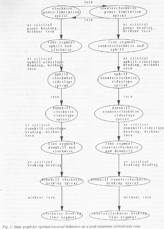
Theorem 3.1: Fig. 1 correctly represents all possible
behavioral states and transitions for optimal paths on a vertical-axis
peak-maximum cone surface. Proof: By Lemma 3.3, the only possible non-line
optimal behaviors are the eight kinds of spirals, for which the ![]() �is constant.
Otherwise,
�is constant.
Otherwise, ![]() �must
increase for clockwise paths, and decrease for counterclockwise paths by Lemma
3.2. By definition, paths cannot have a lesser
�must
increase for clockwise paths, and decrease for counterclockwise paths by Lemma
3.2. By definition, paths cannot have a lesser ![]() �than
�than ![]() . A path following a power spiral can
either make a transition to the other power spiral using Lemma 3.1, or can make
a transition at any time to a straight line segment uphill. From this latter
state no transitions are possible by Lemmas 3.1 and 3.3 until
. A path following a power spiral can
either make a transition to the other power spiral using Lemma 3.1, or can make
a transition at any time to a straight line segment uphill. From this latter
state no transitions are possible by Lemmas 3.1 and 3.3 until ![]() �is reached, at which
point an optimal path can make a transition to an uphill sideslope (
�is reached, at which
point an optimal path can make a transition to an uphill sideslope (![]() ) spiral. Then at any
point subsequently, a transition can be made to a downhill sideslope (
) spiral. Then at any
point subsequently, a transition can be made to a downhill sideslope (![]() ) spiral by Lemma 3.1,
and then by symmetry, at any point a further transition can be made to a
downhill straight line. Lemma 3.4 prevents the transition from the
) spiral by Lemma 3.1,
and then by symmetry, at any point a further transition can be made to a
downhill straight line. Lemma 3.4 prevents the transition from the ![]() �spiral back to the
�spiral back to the ![]() �spiral. Eventually if
the straight line is continued, the braking heading will be reached, at which
point a transition can be made to a braking (
�spiral. Eventually if
the straight line is continued, the braking heading will be reached, at which
point a transition can be made to a braking (![]() ) spiral. This spiral can be followed an
arbitrary length, at which point a final transition to a braking downhill line
segment can be made. In all these transitions, except those between power
spirals, a clockwise or counterclockwise sense of the path is preserved. (This
theorem can also be proved by modeling the cone as an infinite-sided polyhedron
and using the theorems of (Rowe and Ross 1990).) QED.
) spiral. This spiral can be followed an
arbitrary length, at which point a final transition to a braking downhill line
segment can be made. In all these transitions, except those between power
spirals, a clockwise or counterclockwise sense of the path is preserved. (This
theorem can also be proved by modeling the cone as an infinite-sided polyhedron
and using the theorems of (Rowe and Ross 1990).) QED.
This envisionment diagram may be used with the start state specified or unspecified. If the starting heading is known, only state sequences beginning in its qualitative state can be considered. But most agents following a path can turn in any permissible direction to start the path, in which case the starting heading can be any permissible heading and the starting state can be any permissible state. We assume the latter for the rest of this paper.
Some of the states in the Figure may not be possible based
on ![]() ,
, ![]() , and
, and ![]() . If
. If ![]() �is a braking heading,
the critical braking heading
�is a braking heading,
the critical braking heading ![]() would lead to overturn, and there is no
permissible nonbraking downhill heading; so the "line segment
downhill" and "downhill braking spiral" states must be deleted,
and the transition from the "downhill sideslope spiral" states must
go to the "braking line segment" states. If power limitations do not
apply to a vehicle, then the power-spiral states must be eliminated; if
sideslope limitations do not apply, then the sideslope-spiral states must be
eliminated, and the nonbraking line-segment states coalesced; if braking
limitations do not apply, then the two braking states must be eliminated.
would lead to overturn, and there is no
permissible nonbraking downhill heading; so the "line segment
downhill" and "downhill braking spiral" states must be deleted,
and the transition from the "downhill sideslope spiral" states must
go to the "braking line segment" states. If power limitations do not
apply to a vehicle, then the power-spiral states must be eliminated; if
sideslope limitations do not apply, then the sideslope-spiral states must be
eliminated, and the nonbraking line-segment states coalesced; if braking
limitations do not apply, then the two braking states must be eliminated.
The transitions marked "turn" in Fig. 1 are also not always possible for some vehicles; see Section 6.
4. Additional constraints on optimal paths on the vertical-axis peak-maximum cone
The previous section as summarized in Fig. 1 specified conditions on transitions between particular optimal-path behaviors. (Kuipers 1986) explains that although they are powerful tools, such finite-state envisionment diagrams give necessary but not sufficient restrictions on real-world behavior. This section will prove additional, more complex conditions on optimal paths that will rule out further possibilities, plus some necessary facts about the geometry of lines and spirals, and some other general principles.
4.1 Some constraints on behavioral sequences
Lemma 4.1 (Half-plane Lemma): No optimal path from S to G need cross the line through S and the cone vertex O, with the one exception of paths following power-limitation spirals when turns across the power-limitation headings are not permitted. Proof: See Fig. 2. Let L be the line through S and O. We assume an optimal path crossing L exists, then show a contradiction. If such a path P exists, there much exist a mirror-symmetric path P' from S to some G', where P' takes the same headings as P but counterclockwise where P turned clockwise, and where G' is the mirror reflection of G across the L. Because P and P' are symmetric, they must intersect at a point I on L that is the same cost from S along either path. Thus if turns across impermissible-heading ranges are permitted, an optimal path need never cross L because it could switch from P' to P at I, staying entirely to one side of L. Furthermore, the abrupt turn could probably be shortcut, giving a still lower cost to G.
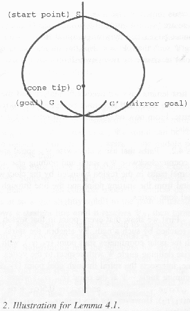
But now suppose that turns across impermissible-heading
ranges (called Type-III turns in (Rowe and Ross 1990)) are not permitted. Even
so, the Shortcut Suboptimality Condition can be used to rule out most paths crossing
the center line. The path behaviors of P and P' at I must be mirror-symmetric.
If both are braking segments, then the path following P' to I and then P to G
can be shortcut near I by a straight line segment that is still more downhill
and shorter, and thus more desirable (and its heading cannot be impermissible
if the original headings are permissible). If both paths at I have permissible
downhill nonbraking behaviors, there also must exist straight-line shortcuts
across the turn at I that head still farther downhill and are therefore
desirable and permissible. If both behaviors at I are ![]() spirals, then G and G' must lie
within the closed shape created by P and P' between S and I, and shortcutting
the turn at I will be slightly more uphill, hence permissible and shorter. A
similar argument applies to straight-segment-uphill behavior of the two paths
at I. So the only exception is when turns across impermissible-heading ranges
are not permitted, there are power-limitation headings, and G is a point that
cannot be reached by a single spiral from S with heading �
spirals, then G and G' must lie
within the closed shape created by P and P' between S and I, and shortcutting
the turn at I will be slightly more uphill, hence permissible and shorter. A
similar argument applies to straight-segment-uphill behavior of the two paths
at I. So the only exception is when turns across impermissible-heading ranges
are not permitted, there are power-limitation headings, and G is a point that
cannot be reached by a single spiral from S with heading �![]() �such that
�such that ![]() ; this means that G must be a
point reachable by two power-limitation spirals. QED.
; this means that G must be a
point reachable by two power-limitation spirals. QED.
The first Lemma says we need only analyze half the terrain, as the other half's optimal behaviors are mirror-symmetric. From now on, all results will refer to the right half-plane.
Lemma 4.2: Paths that use a clockwise ![]() �spiral and then a counterclockwise
�spiral and then a counterclockwise
![]() �spiral and
nothing else are the optimal paths in the region bounded by the clockwise
�spiral and
nothing else are the optimal paths in the region bounded by the clockwise ![]() �spiral from the
starting point and the line through the start and cone vertex. Proof: First we
show that every point in that region can be reached by such a path. By algebra,
the spiral through the polar-coordinates start point
�spiral from the
starting point and the line through the start and cone vertex. Proof: First we
show that every point in that region can be reached by such a path. By algebra,
the spiral through the polar-coordinates start point ![]() , with clockwise defining angle
, with clockwise defining angle ![]() with respect to the
vertex of the cone, intersects the spiral through goal point
with respect to the
vertex of the cone, intersects the spiral through goal point ![]() �with defining angle
�with defining angle ![]() �at the point
�at the point ![]() �where
�where ![]() �and
�and ![]() . But for this case
. But for this case ![]() �since that is
equivalent to
�since that is
equivalent to ![]() ,
and
,
and ![]() �by
definition,
�by
definition, ![]() ,
and
,
and ![]() �by
Lemma 4.1. Hence some path that takes the clockwise
�by
Lemma 4.1. Hence some path that takes the clockwise ![]() �spiral, then the
counterclockwise spiral, can reach every point in the region bounded by the
clockwise
�spiral, then the
counterclockwise spiral, can reach every point in the region bounded by the
clockwise ![]() �spiral
and the y-axis.
�spiral
and the y-axis.
Now we must show no other path can be optimal in that
region. Since the path described consists only of uphill spirals, the path cost
by our second cost function in section 2.1 is proportional to the path length, ![]() �since
�since ![]() . No path can ascend
as fast as the power spirals, so any path that uses line segments could not be
lower-cost. No path could use the counterclockwise
. No path can ascend
as fast as the power spirals, so any path that uses line segments could not be
lower-cost. No path could use the counterclockwise ![]() �spiral first because that would
take it into the other half-plane, and it would need to then cross the SO line
to reach the goal, violating Lemma 4.1. Any path that uses only power spirals
but not just two would cost the same as the two-spiral path since the secants
of all segments are the same, but would have more turn points, so would be
suboptimal by our definition in section 2.1. Hence no possible behavior sequence
that can be derived from Fig. 1 can be as optimal as the two-spiral one. QED.
�spiral first because that would
take it into the other half-plane, and it would need to then cross the SO line
to reach the goal, violating Lemma 4.1. Any path that uses only power spirals
but not just two would cost the same as the two-spiral path since the secants
of all segments are the same, but would have more turn points, so would be
suboptimal by our definition in section 2.1. Hence no possible behavior sequence
that can be derived from Fig. 1 can be as optimal as the two-spiral one. QED.
Lemma 4.3: The only optimal abrupt turns across a
sideslope-impermissibility heading range are from a ![]() �spiral of nontrivial arclength
to a
�spiral of nontrivial arclength
to a ![]() �spiral
of nontrivial arclength. Proof: Such turns must be from
�spiral
of nontrivial arclength. Proof: Such turns must be from ![]() �to
�to ![]() �by Lemma 3.4. We now prove that
neither of the path segments near the turn can be a line segment, by using the
Shortcut Suboptimality Condition with infinitesimally-short sideslope spirals
as shortcuts across the path turn. Let the spiral shortcut from point P1 to
point P3, where the allegedly optimal path turns at P2 from
�by Lemma 3.4. We now prove that
neither of the path segments near the turn can be a line segment, by using the
Shortcut Suboptimality Condition with infinitesimally-short sideslope spirals
as shortcuts across the path turn. Let the spiral shortcut from point P1 to
point P3, where the allegedly optimal path turns at P2 from ![]() �to
�to ![]() , and P1 and P3 are
infinitesimally close to P2. Let
, and P1 and P3 are
infinitesimally close to P2. Let ![]() �be the radius of P1 from the cone vertex,
�be the radius of P1 from the cone vertex,
![]() �for P2, and
�for P2, and ![]() �for P3. Let
�for P3. Let ![]() �be the angle between
the radii
�be the angle between
the radii ![]() �and
�and
![]() , and
, and ![]() �be the angle between
the radii
�be the angle between
the radii ![]() �and
�and
![]() .
.
Case 1, the path turn is at the junction of two straight-line
segments, and �![]() �is
nonbraking: using the second cost function in section 2.1, we need to show that
the length of the turn detour is worse than the length of an uphill spiral
shortcut, or
�is
nonbraking: using the second cost function in section 2.1, we need to show that
the length of the turn detour is worse than the length of an uphill spiral
shortcut, or ![]() �.
That is equivalent to showing
�.
That is equivalent to showing ![]() �. If we replace the exponential by three
terms of its series, we get after simplification
�. If we replace the exponential by three
terms of its series, we get after simplification ![]() . Since
. Since ![]() �and
�and ![]() �must hold.
�must hold.
Case 2, the path turn is the transition from a straight line
to a spiral, and ![]() �is
nonbraking: we must show
�is
nonbraking: we must show ![]() . That is equivalent to showing
. That is equivalent to showing ![]() �, which after
approximating the exponential series by their first two terms is
�, which after
approximating the exponential series by their first two terms is ![]() , or
, or ![]() .
.
Case 3, the path turn is the transition from an uphill spiral to a straight line downhill, and the downhill initial heading is nonbraking: this is just the mirror image of case 2, and is proved similarly.
Case 4, the path turn is the transition from some uphill
behavior (either a straight line or a ![]() �spiral) to a straight line downhill, and �
�spiral) to a straight line downhill, and �![]() �is braking (note the
�is braking (note the ![]() �heading cannot be
braking, because all braking headings are downhill): then a
�heading cannot be
braking, because all braking headings are downhill): then a ![]() �shortcut spiral from P1 to P3
is braking as well as the path from P2 to P3. Hence by the first cost function
of section 2.1, the spiral from P1 to P3 costs nothing, while the turn path
costs something from P1 to P2 because that is uphill and guaranteed to be
nonbraking.
�shortcut spiral from P1 to P3
is braking as well as the path from P2 to P3. Hence by the first cost function
of section 2.1, the spiral from P1 to P3 costs nothing, while the turn path
costs something from P1 to P2 because that is uphill and guaranteed to be
nonbraking.
Case 5, the path turn is the transition from a straight line
uphill to a braking �![]() �spiral:
then there is a
�spiral:
then there is a ![]() �spiral
shortcut, and it must be even better than the one in Case 2 since section 2.1
showed
�spiral
shortcut, and it must be even better than the one in Case 2 since section 2.1
showed ![]() �for
a braking path.
�for
a braking path.
Lemma 4.4: Paths from S to G that start in an uphill
straight segment, make a non-turn transition to a ![]() �spiral, and then turn to a nonbraking
�spiral, and then turn to a nonbraking ![]() �spiral are not optimal
unless the middle (uphill) spiral traverses an angle with respect to the cone
vertex of exactly
�spiral are not optimal
unless the middle (uphill) spiral traverses an angle with respect to the cone
vertex of exactly ![]() .
Proof: We will use the Shortcut Suboptimality Condition with a
.
Proof: We will use the Shortcut Suboptimality Condition with a ![]() -spiral
"shortcut". See Fig. 3. Use polar coordinates and let the radii of
the starting point S, the transition to
-spiral
"shortcut". See Fig. 3. Use polar coordinates and let the radii of
the starting point S, the transition to ![]() �spiral, the transition to
�spiral, the transition to ![]() �spiral, and goal point
G be
�spiral, and goal point
G be ![]() �and
�and ![]() �respectively; let the
angles between these radii be
�respectively; let the
angles between these radii be ![]() , and
, and ![]() . Since both paths are all nonbraking,
their length can be taken as their cost, and using the Law of Sines and the
arclength formula for spirals, the length of the three-behavior path is
. Since both paths are all nonbraking,
their length can be taken as their cost, and using the Law of Sines and the
arclength formula for spirals, the length of the three-behavior path is ![]() . We can eliminate
. We can eliminate ![]() �and
�and ![]() �by the mathematics of
spirals and the substitution of
�by the mathematics of
spirals and the substitution of ![]() , to get after rearrangement and
simplification:
, to get after rearrangement and
simplification:
![]()
For particular start (S) and goal (G) points, this is a
function of one variable, ![]() . Its first derivative with respect to
. Its first derivative with respect to ![]() �is:
�is:
![]()
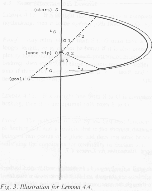
We propose a shortcut across this path which is a ![]() �spiral from a point on
the line segment infinitesimally close (this is exaggerated in Fig. 3) to
line-spiral junction to a point on the
�spiral from a point on
the line segment infinitesimally close (this is exaggerated in Fig. 3) to
line-spiral junction to a point on the ![]() �spiral infinitesimally close to its
junction with the
�spiral infinitesimally close to its
junction with the ![]() �spiral.
That is a special case of the formula where
�spiral.
That is a special case of the formula where ![]() �and
�and ![]() . Then
. Then ![]() , but the second derivative there is
greater than zero (after some algebra) if
, but the second derivative there is
greater than zero (after some algebra) if
![]()
which is equivalent to ![]() . This means that any three-behavior path
in the form of line segment to
. This means that any three-behavior path
in the form of line segment to ![]() �spiral to
�spiral to ![]() �spiral can be shortcut by an infinitesimally-close
�
�spiral can be shortcut by an infinitesimally-close
�![]() �spiral if
the middle portion subtends less than
�spiral if
the middle portion subtends less than ![]() .
.
Now we must prove the angle must be exactly ![]() �degrees. Suppose the
middle portion of a path subtended more than
�degrees. Suppose the
middle portion of a path subtended more than ![]() . Then consider a nearly identical path
that starts at an angle slightly uphill to the path in question, following a
straight line until it reaches �
. Then consider a nearly identical path
that starts at an angle slightly uphill to the path in question, following a
straight line until it reaches �![]() , then turns to a
, then turns to a ![]() �spiral and intersects the path
in question. For such a path
�spiral and intersects the path
in question. For such a path ![]() �is not zero but the condition
�is not zero but the condition ![]() �holds in the limit.
Substituting into the equation for
�holds in the limit.
Substituting into the equation for ![]() , we find after some algebra that the new
path will be better than the old path if
, we find after some algebra that the new
path will be better than the old path if ![]() . �We can pick the start arbitrarily close
to the first transition, so in the limit
. �We can pick the start arbitrarily close
to the first transition, so in the limit ![]() �for the new path to be suboptimal. QED.
�for the new path to be suboptimal. QED.
Lemma 4.5: Paths from S to G that start in an uphill
straight segment, make a non-turn transition to a ![]() �spiral, and then turn to a braking
�spiral, and then turn to a braking ![]() �spiral are not optimal
unless the middle (uphill) spiral subtends an angle with respect to the cone
vertex of exactly
�spiral are not optimal
unless the middle (uphill) spiral subtends an angle with respect to the cone
vertex of exactly ![]() .
�Proof: Similar to the last Lemma, but now the cost of the
.
�Proof: Similar to the last Lemma, but now the cost of the ![]() �spiral is increased by the
"virtual braking" cost, the second cost definition in section 2.1.
For the braking episode
�spiral is increased by the
"virtual braking" cost, the second cost definition in section 2.1.
For the braking episode ![]() �is constant, and the virtual cost is
proportional to the length of the path, where the constant of proportionality
is the negative of the tangent of the downhill slope divided by
�is constant, and the virtual cost is
proportional to the length of the path, where the constant of proportionality
is the negative of the tangent of the downhill slope divided by ![]() . �By solid geometry
this constant is
. �By solid geometry
this constant is ![]() ,
where
,
where ![]() �is the
inclination of the cone. By the definition of the
�is the
inclination of the cone. By the definition of the ![]() ,
, ![]() . Hence the constant is
. Hence the constant is ![]() .
.
After some algebra, this modified cost for the downhill
segment has just one effect on the formula for ![]() �in the last Lemma, that of adding an
extra multiplier of
�in the last Lemma, that of adding an
extra multiplier of ![]() �after
the plus sign. By similar analysis to the previous Lemma, the conditions under
which a second derivative will be positive give a bound which is the
�after
the plus sign. By similar analysis to the previous Lemma, the conditions under
which a second derivative will be positive give a bound which is the ![]() �in the statement of
this Lemma. The angle must be exactly
�in the statement of
this Lemma. The angle must be exactly ![]() �degrees by the same analysis used in
Lemma 4.4. QED.
�degrees by the same analysis used in
Lemma 4.4. QED.
Observations: By experiment, we can say ![]() . But
. But ![]() �is unboundedly large for
�is unboundedly large for ![]() close to
close to ![]() , so it may be greater
than the maximum of �
, so it may be greater
than the maximum of �![]() �necessary
to keep behavioral boundaries in one halfplane.
�necessary
to keep behavioral boundaries in one halfplane.
Lemma 4.6: Optimal paths that go from a ![]() �spiral to a
�spiral to a ![]() �spiral to a nonbraking downhill
straight line must traverse an angle of exactly �
�spiral to a nonbraking downhill
straight line must traverse an angle of exactly �![]() �with respect to the cone vertex in their
middle (downhill-spiral) portion. Proof: Since no braking is involved, such
path portions cost the same in the reverse direction, in which case Lemma 4.4
applies and its conditions for a spiral shortcut. QED.
�with respect to the cone vertex in their
middle (downhill-spiral) portion. Proof: Since no braking is involved, such
path portions cost the same in the reverse direction, in which case Lemma 4.4
applies and its conditions for a spiral shortcut. QED.
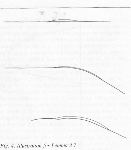
Lemma 4.7: Optimal paths with braking line segments must be
braking for their entire length. Proof: we will show that in each of the three
possible cases (illustrated in Fig. 4), a ![]() -spiral "shortcut" across the
path gives lower cost. In Case 1, assume that the braking line segment is
preceded immediately by a nonbraking line segment; construct the spiral
shortcut from a point on the nonbraking segment infinitesimally close to the
junction, and it must intersect the braking segment at a point on it
infinitesimally close to the junction. In case 2, assume the braking line
segment is preceded by a
-spiral "shortcut" across the
path gives lower cost. In Case 1, assume that the braking line segment is
preceded immediately by a nonbraking line segment; construct the spiral
shortcut from a point on the nonbraking segment infinitesimally close to the
junction, and it must intersect the braking segment at a point on it
infinitesimally close to the junction. In case 2, assume the braking line
segment is preceded by a ![]() �spiral and a nonbraking line segment
(which requires that the
�spiral and a nonbraking line segment
(which requires that the ![]() �heading be nonbraking); then construct
the shortcut spiral from a point on the nonbraking segment infinitesimally
close to its junction with the
�heading be nonbraking); then construct
the shortcut spiral from a point on the nonbraking segment infinitesimally
close to its junction with the ![]() spiral to a point on the braking segment
infinitesimally close to transition from the
spiral to a point on the braking segment
infinitesimally close to transition from the ![]() �spiral. In case 3, assume
�spiral. In case 3, assume ![]() �is braking, and the
braking line segment is preceded by the
�is braking, and the
braking line segment is preceded by the ![]() �spiral and prior to that, the
�spiral and prior to that, the ![]() �spiral. Then construct
the spiral shortcut from a point on the uphill spiral infinitesimally close to
the turn to a point on the braking line segment infinitesimally close to its
transition from a sideslope spiral. In each of the cases described, the spiral
shortcut is guaranteed to connect the points so described because it stays
outside the allegedly optimal path (that is, away from the cone vertex), and
maintains a
�spiral. Then construct
the spiral shortcut from a point on the uphill spiral infinitesimally close to
the turn to a point on the braking line segment infinitesimally close to its
transition from a sideslope spiral. In each of the cases described, the spiral
shortcut is guaranteed to connect the points so described because it stays
outside the allegedly optimal path (that is, away from the cone vertex), and
maintains a ![]() �less
than all other braking
�less
than all other braking ![]() , so the braking line segment must
eventually intersect it. But this spiral shortcut is a lower-cost path, by the
first cost function in section 2.1, than the allegedly optimal one since in
each of the three cases the shortcut costs zero, whereas some nonzero behavior
is included, hence some behavior of nonzero cost, in the detours. QED.
, so the braking line segment must
eventually intersect it. But this spiral shortcut is a lower-cost path, by the
first cost function in section 2.1, than the allegedly optimal one since in
each of the three cases the shortcut costs zero, whereas some nonzero behavior
is included, hence some behavior of nonzero cost, in the detours. QED.
4.2. Proofs about the nature of behavioral boundaries
Lemma 4.8: The locus of all points reached by traveling
clockwise with respect to the cone vertex in a straight line until a fixed
angle ![]() �is
reached with respect to the angle between the path and the cone vertex is a
circular arc through the cone vertex and the starting point, an arc which
subtends an angle
�is
reached with respect to the angle between the path and the cone vertex is a
circular arc through the cone vertex and the starting point, an arc which
subtends an angle ![]() �about
the cone vertex. Proof: This follows from the fact that the angle from the
starting point, to any point on the locus, then to the cone vertex must be
�about
the cone vertex. Proof: This follows from the fact that the angle from the
starting point, to any point on the locus, then to the cone vertex must be ![]() , and the geometrical
principle that the locus of all points whose inscribed angle is fixed is an arc
of a circle. QED.
, and the geometrical
principle that the locus of all points whose inscribed angle is fixed is an arc
of a circle. QED.
Lemma 4.9: All points reachable by following a ![]() spiral (
spiral (![]() being arbitrary), then
a tangent line to it until
being arbitrary), then
a tangent line to it until ![]() , lie on another
, lie on another ![]() �spiral whose radius is always a
constant multiplier
�spiral whose radius is always a
constant multiplier ![]() �of
the radius of the original
�of
the radius of the original ![]() �spiral. Proof: By the Law of Sines, the
radius at an endpoint of such a path must be the radius at the point of
tangency times
�spiral. Proof: By the Law of Sines, the
radius at an endpoint of such a path must be the radius at the point of
tangency times ![]() �.
This multiplier is a constant for everywhere on the spiral, so the locus of the
endpoints is itself a spiral, angle-shifted as well as being scaled larger. The
angle-shifting accounts for another factor of �
�.
This multiplier is a constant for everywhere on the spiral, so the locus of the
endpoints is itself a spiral, angle-shifted as well as being scaled larger. The
angle-shifting accounts for another factor of �![]() . QED.
. QED.
Lemma 4.10: Suppose a curve in polar coordinates is ![]() . Then the locus of all
points reachable by starting at a point on this curve and pursuing a clockwise
spiral with constant heading
. Then the locus of all
points reachable by starting at a point on this curve and pursuing a clockwise
spiral with constant heading ![]() �through a fixed rotation of
�through a fixed rotation of ![]() �about the cone vertex
is
�about the cone vertex
is ![]() . Proof:
Simple since the spiral acts as a transformation mapping each point to one that
is
. Proof:
Simple since the spiral acts as a transformation mapping each point to one that
is ![]() �angular
measure clockwise and
�angular
measure clockwise and ![]() �ratio closer to the origin. QED.
�ratio closer to the origin. QED.
4.3 Some miscellaneous lemmas
Lemma 4.11: If a straight line from S to G is completely
nonbraking, then it is the optimal path from S to G. Proof: Any other path ![]() �from S to G must have
a longer length, so
�from S to G must have
a longer length, so ![]() �cannot
be better if it is also completely nonbraking. Otherwise, if portions of
�cannot
be better if it is also completely nonbraking. Otherwise, if portions of ![]() �are braking, then the
cost of those portions must be higher than if their cost were nonbraking, therefore
�are braking, then the
cost of those portions must be higher than if their cost were nonbraking, therefore
![]() , hence
, hence ![]() . QED.
. QED.
Lemma 4.12: If a straight line from S to G is completely braking, then it is the optimal path from S to G. Proof: the path cost is zero by the first cost function of section 2.1, and a straight line is the shortest distance between two points on a plane, and does not turn, hence satisfying the conditions for optimality in section 2.1. QED.
Lemma 4.13 (Monotonicity Lemma): Assume an optimal path ![]() �from S to G is found
assuming a set of vehicle limitations V1, and additional restrictions are
imposed on V1 to create a new set of vehicle limitations V2. The restrictions
could be adding power limitations, adding sideslope limitations, widening the
heading interval for either, or widening the braking-heading range. Then if
�from S to G is found
assuming a set of vehicle limitations V1, and additional restrictions are
imposed on V1 to create a new set of vehicle limitations V2. The restrictions
could be adding power limitations, adding sideslope limitations, widening the
heading interval for either, or widening the braking-heading range. Then if ![]() �is unchanged by the
additional limitations of V2, it remains the optimal path from S to G in V2.
Proof: the limitations cannot decrease the cost of any path, so if P was
optimal before and remains unchanged in cost and permissibility, it must remain
optimal. QED.
�is unchanged by the
additional limitations of V2, it remains the optimal path from S to G in V2.
Proof: the limitations cannot decrease the cost of any path, so if P was
optimal before and remains unchanged in cost and permissibility, it must remain
optimal. QED.
Lemma 4.14: Suppose a set of points R is optimally reached
by a sequence of qualitative states S other than two power spirals. Then R is
bounded to the side away from the cone vertex by the curve created by deleting
the first element of S and following each of the behaviors in the subsequent
list to the maximum extent permissible (the maximum length of a line segment
until a critical heading is reached, or ![]() �or
�or ![]() �for a
�for a ![]() �or
�or ![]() �spiral). Proof: Each possible behavior in
the sequence S must have a higher or equal �
�spiral). Proof: Each possible behavior in
the sequence S must have a higher or equal �![]() �than the preceding behavior in the
sequence. Thus if the first behavior is removed from the sequence, the
associated path must start out with greater
�than the preceding behavior in the
sequence. Thus if the first behavior is removed from the sequence, the
associated path must start out with greater ![]() �than any path in the region defined by S.
But optimal paths cannot cross. Hence the shortened sequence gives a path that
must remain outside the behavioral region. QED.
�than any path in the region defined by S.
But optimal paths cannot cross. Hence the shortened sequence gives a path that
must remain outside the behavioral region. QED.
5. Mapping of the cone surface into behavioral regions
We will now use the results of the previous sections to construct "cone maps" with respect to a fixed starting point, partitions of the azimuth projection of the vertical-axis peak-maximum cone surface into "behavioral regions". A behavioral region is a connected map area corresponding to a connected area of the cone surface such that if a goal point is located anywhere within the region, the sequence of behaviors followed by an optimal path from the fixed start point to that goal point is the same; a behavior is a state of Fig. 1. We have previously used behavioral regions for the weighted-region problem in (Alexander and Rowe 1990).
The six main cases we will examine and the six theorems we
will prove are: (5.1) braking phenomena only; (5.2) power-limitation uphill
phenomena only; (5.3) braking and power-limitation phenomena; (5.4)
sideslope-overturn phenomena only; (5.5) power-limitation, sideslope, and
braking phenomena when ![]() �is braking; and (5.6) power-limitation,
sideslope, and braking phenomena when
�is braking; and (5.6) power-limitation,
sideslope, and braking phenomena when ![]() �is not braking. We will consider the
cases in this order. Figs. 8-18 show the six maps; Fig. 5 defines the vertices
in the maps, Fig. 6 defines the curve types in the maps, and Fig. 7 lists the
behaviors associated with each region behavior code number. This section is
simplified from (Rowe and Kanayama 1992), where proofs are given for other
cases too.
�is not braking. We will consider the
cases in this order. Figs. 8-18 show the six maps; Fig. 5 defines the vertices
in the maps, Fig. 6 defines the curve types in the maps, and Fig. 7 lists the
behaviors associated with each region behavior code number. This section is
simplified from (Rowe and Kanayama 1992), where proofs are given for other
cases too.
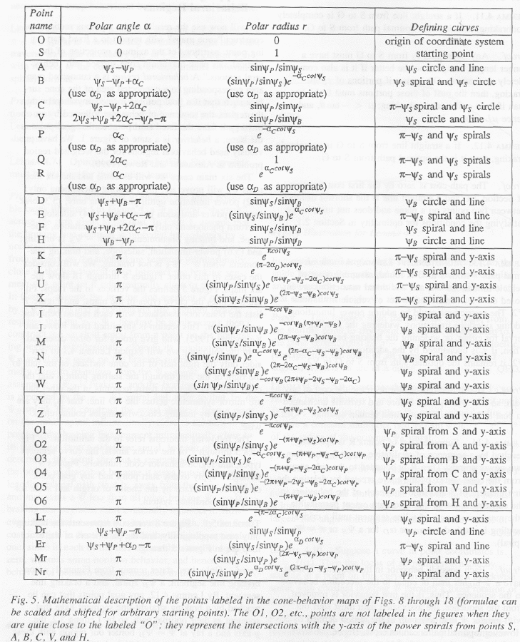
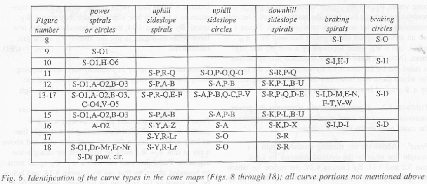
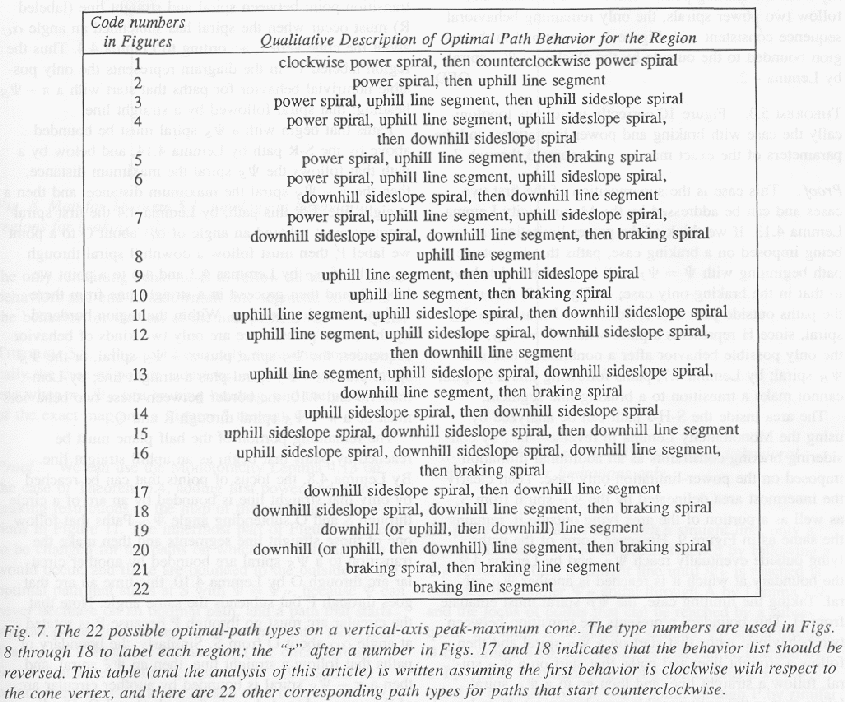
In the following we will exploit Lemma 4.1 to consider only the right half of the cone surface, the half to the right of the line through the starting point S and the cone vertex O. Optimal paths to points in the other half are mirror-symmetric across the S-O line; that is, they are constructed by making clockwise angles counterclockwise.
The following theorems refer to the definitions in Figs. 5-7 of the vertex labels, the curve-segment types, and region-behavior code numbers. Figs. 5-7 apply to any start point and any goal point on any cone surface by the choice of origin and scale for the polar coordinate system.
Theorem 5.1: Fig. 8 correctly represents the braking-only
case topologically, and the parameters of the exact map are in Figs. 5-7.
Proof: Only three states remain from Fig. 1: a nonbraking line segment, a ![]() �spiral, and a braking
line segment. By Lemma 4.12, any goal points that can be reached by a braking
straight-line segment have that segment as their optimal path, so by Lemma 3.2,
the y-axis and a ray at
�spiral, and a braking
line segment. By Lemma 4.12, any goal points that can be reached by a braking
straight-line segment have that segment as their optimal path, so by Lemma 3.2,
the y-axis and a ray at ![]() �border our region with these optimal
paths. By Lemmas 4.11 and 4.8, a circular arc through S and O subtending angle
�border our region with these optimal
paths. By Lemmas 4.11 and 4.8, a circular arc through S and O subtending angle ![]() �with respect to the
cone vertex bounds the region whose optimal path is a nonbraking straight line
from the starting point. The only remaining behavior sequences consistent with
Fig. 1 are an initially-uphill line segment followed by a
�with respect to the
cone vertex bounds the region whose optimal path is a nonbraking straight line
from the starting point. The only remaining behavior sequences consistent with
Fig. 1 are an initially-uphill line segment followed by a ![]() �spiral, and a
�spiral, and a ![]() �spiral followed by a
braking line segment (note the 3-behavior sequence line-spiral-line is ruled
out by Lemma 4.7). By Lemma 4.14, the regions for which these two behaviors are
optimal are separated by a
�spiral followed by a
braking line segment (note the 3-behavior sequence line-spiral-line is ruled
out by Lemma 4.7). By Lemma 4.14, the regions for which these two behaviors are
optimal are separated by a ![]() spiral from the starting point. QED.
spiral from the starting point. QED.
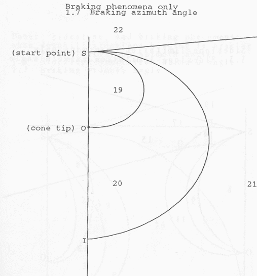
Theorem 5.2: Fig. 9 correctly represents the
power-limitation-only case topologically, and the parameters of the exact map
are in Figs. 5-7. Proof: Above the ray running southeast from S a straight line
must be the optimal behavior by Lemmas 3.2 and 4.11. By Lemma 4.14, the region
for which the optimal path is a power-limitation spiral followed by a straight
line must be bounded to the outside by this ray from the starting point with ![]() . Paths that follow two
power spirals, the only remaining behavioral sequence consistent with Fig. 1,
are optimal in the region bounded to the outside by the clockwise
. Paths that follow two
power spirals, the only remaining behavioral sequence consistent with Fig. 1,
are optimal in the region bounded to the outside by the clockwise ![]() �spiral by Lemma 4.2.
QED.
�spiral by Lemma 4.2.
QED.
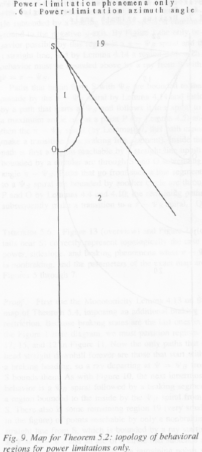
Theorem 5.3: Fig. 10 correctly represents topologically the
case with braking and power limitations, and the parameters of the exact map
are in Figs. 5-7. Proof: This case is the superposition of the first two cases
and can be addressed by the Monotonicity Lemma, Lemma 4.13. If we think of the
power limitations as being imposed on a braking case, paths that lie outside a
path beginning with ![]() �will
have identical behavior to that in the braking-only case; in Fig. 10, that
means the paths outside path S-H-J. Portion H-J must be a
�will
have identical behavior to that in the braking-only case; in Fig. 10, that
means the paths outside path S-H-J. Portion H-J must be a ![]() spiral since H represents a
place where
spiral since H represents a
place where ![]() �and
the only possible behavior after a nonbraking line is a
�and
the only possible behavior after a nonbraking line is a ![]() �spiral; by Lemma 4.7, paths
following this
�spiral; by Lemma 4.7, paths
following this ![]() �spiral
cannot make a transition to a braking line segment.
�spiral
cannot make a transition to a braking line segment.
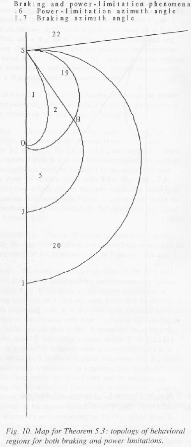
The area inside the S-H-J path can be analyzed by using the
Monotonicity Lemma in reverse, by considering braking constraints as an
additional limitation imposed on the power-limitation-only case. Then clearly
the innermost area delineated by the ![]() �spiral from S remains the same as in Fig.
9 as well as a portion of the area lying outside it. But some of the paths
lying outside eventually reach
�spiral from S remains the same as in Fig.
9 as well as a portion of the area lying outside it. But some of the paths
lying outside eventually reach ![]() , and by Lemma 4.9 the boundary at which
it is reached is another
, and by Lemma 4.9 the boundary at which
it is reached is another ![]() �spiral. Taking the limiting case, the
�spiral. Taking the limiting case, the ![]() �spiral must emanate
from H. This boundary represents the transition between two behaviors: paths
that start on a
�spiral must emanate
from H. This boundary represents the transition between two behaviors: paths
that start on a ![]() �spiral
and then follow a straight line, and paths that start on a
�spiral
and then follow a straight line, and paths that start on a ![]() �spiral, follow a straight line,
and then go to a
�spiral, follow a straight line,
and then go to a ![]() �spiral
(since that is the only possible next behavior). Note by Lemma 4.7 that these
paths cannot make a further transition to a braking line segment once they
start a
�spiral
(since that is the only possible next behavior). Note by Lemma 4.7 that these
paths cannot make a further transition to a braking line segment once they
start a ![]() spiral.
By Lemma 4.14, the outer boundary of this new three-behavior region is just the
H-to-J
spiral.
By Lemma 4.14, the outer boundary of this new three-behavior region is just the
H-to-J ![]() �spiral
just constructed. QED.
�spiral
just constructed. QED.
Theorem 5.4: Fig. 11 correctly represents topologically the
case of only sideslope limitations, and the parameters of the exact map are in
Figs. 5-7. Proof: Nothing prevents paths that start with a ![]() �greater than
�greater than ![]() �from continuing in a
straight line as long as they like, so the area northwest of S and above a ray
at that
�from continuing in a
straight line as long as they like, so the area northwest of S and above a ray
at that ![]() �must
be reachable by straight-line segments. Paths that start out with a
�must
be reachable by straight-line segments. Paths that start out with a ![]() �spiral must be bounded
above by that ray by Lemma 4.14, and below by the spiral as far as it can be
followed, and then by a downhill straight line according to the state diagram;
the transition point between spiral and straight line (labeled R) must occur
when the spiral has subtended an angle
�spiral must be bounded
above by that ray by Lemma 4.14, and below by the spiral as far as it can be
followed, and then by a downhill straight line according to the state diagram;
the transition point between spiral and straight line (labeled R) must occur
when the spiral has subtended an angle ![]() �about the cone vertex, according to Lemma
4.4. So the region labeled 17 in the diagram represents the only possible
nontrivial behavior for paths that start with a
�about the cone vertex, according to Lemma
4.4. So the region labeled 17 in the diagram represents the only possible
nontrivial behavior for paths that start with a ![]() �heading, that spiral followed by a
straight line.
�heading, that spiral followed by a
straight line.
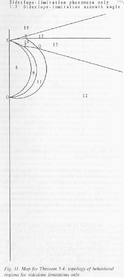
Paths that begin with a ![]() �spiral must be bounded above by the S-R
path by Lemma 4.14, and below by a path that follows the
�spiral must be bounded above by the S-R
path by Lemma 4.14, and below by a path that follows the ![]() �spiral the maximum distance,
then the
�spiral the maximum distance,
then the ![]() �spiral
the maximum distance, and then a straight line. For this path, by Lemma 4.4 the
first spiral segment must subtend an angle of
�spiral
the maximum distance, and then a straight line. For this path, by Lemma 4.4 the
first spiral segment must subtend an angle of ![]() �about O to a point we label P, then must
follow a downhill spiral through an angle of
�about O to a point we label P, then must
follow a downhill spiral through an angle of ![]() �by Lemmas 4.3 and 4.6 to a point we label
Q, and then proceed in a straight line from there without changing heading.
Within the region bordered by these two paths there are only two kinds of
behavior sequences, the
�by Lemmas 4.3 and 4.6 to a point we label
Q, and then proceed in a straight line from there without changing heading.
Within the region bordered by these two paths there are only two kinds of
behavior sequences, the ![]() �spiral plus
�spiral plus ![]() �spiral, or the
�spiral, or the ![]() �spiral, plus
�spiral, plus ![]() �spiral, plus a
straight line; by Lemmas 4.6 and 4.10, the border between these two behaviors
must be a
�spiral, plus a
straight line; by Lemmas 4.6 and 4.10, the border between these two behaviors
must be a ![]() �spiral
through R and Q.
�spiral
through R and Q.
The remaining portion of the half plane must be reached by
paths that begin as an uphill straight line. By Lemma 4.8, the locus of points
that can be reached by only that straight line is bounded by an arc of a circle
through S and O subtending angle ![]() . �Paths that follow one of those straight
line segments and then make the transition to a
. �Paths that follow one of those straight
line segments and then make the transition to a ![]() �spiral are bounded by another circular
arc through O by Lemma 4.10, this time an arc that goes through P but which
subtends the same angle. Note that the circular arc must go through P because P
is rotated angle
�spiral are bounded by another circular
arc through O by Lemma 4.10, this time an arc that goes through P but which
subtends the same angle. Note that the circular arc must go through P because P
is rotated angle ![]() �about
O from S. Similarly, the boundary of paths which follow a straight line, then a
�about
O from S. Similarly, the boundary of paths which follow a straight line, then a
![]() �spiral, and
then a
�spiral, and
then a ![]() �spiral
is bounded by another circular arc of the same subtended angle through O and Q.
Finally, the only remaining behavior is to follow all three of those behaviors
and end in a downhill line segment, so that is the behavior for the rest of the
half-plane. QED.
�spiral
is bounded by another circular arc of the same subtended angle through O and Q.
Finally, the only remaining behavior is to follow all three of those behaviors
and end in a downhill line segment, so that is the behavior for the rest of the
half-plane. QED.
Theorem 5.5: Fig. 12 correctly represents topologically the
case of power, sideslope, and braking phenomena when ![]() �is a braking heading, and the
parameters of the exact map are in Figs. 5-7. Proof: We can use the
Monotonicity Lemma 4.13 on the case of Theorem 5.4, adding first power and then
braking restrictions to the map of the sideslope restrictions in Fig. 11. The
innermost part of Fig. 11 needs to be changed for the paths on which power
limitations would occur, and these are bounded to the outside by the optimal
path that starts at S with �
�is a braking heading, and the
parameters of the exact map are in Figs. 5-7. Proof: We can use the
Monotonicity Lemma 4.13 on the case of Theorem 5.4, adding first power and then
braking restrictions to the map of the sideslope restrictions in Fig. 11. The
innermost part of Fig. 11 needs to be changed for the paths on which power
limitations would occur, and these are bounded to the outside by the optimal
path that starts at S with �![]() , because
, because ![]() �can never decrease on an optimal path and
a path that starts without power limitations can never encounter them later.
Tracing such a path, it will intersect the circle through S and O at a new
point A, then follow a �
�can never decrease on an optimal path and
a path that starts without power limitations can never encounter them later.
Tracing such a path, it will intersect the circle through S and O at a new
point A, then follow a �![]() �spiral to point on the next circle arc B,
and then follow a
�spiral to point on the next circle arc B,
and then follow a ![]() �spiral
until it reaches the y-axis at a new point U. All the paths inside cannot start
with a straight line, only a
�spiral
until it reaches the y-axis at a new point U. All the paths inside cannot start
with a straight line, only a ![]() spiral. The locus of all points reached by
following a
spiral. The locus of all points reached by
following a ![]() spiral
and then a straight line until
spiral
and then a straight line until ![]() �is reached is bounded by another
�is reached is bounded by another ![]() �spiral through A by
Lemma 4.9; and the locus of points that can be reached by a subsequent
�spiral through A by
Lemma 4.9; and the locus of points that can be reached by a subsequent ![]() �spiral are bounded by
another
�spiral are bounded by
another ![]() �spiral
through B by Lemma 4.10; and the locus that can be reached by a
�spiral
through B by Lemma 4.10; and the locus that can be reached by a ![]() �spriral, a straight
line, a
�spriral, a straight
line, a ![]() �spiral,
plus a
�spiral,
plus a ![]() �spiral
is bounded by a
�spiral
is bounded by a ![]() �spiral
through P by similar reasoning.
�spiral
through P by similar reasoning.
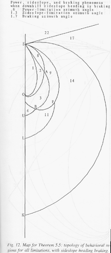
As for the effect of braking restrictions, they will change
the nature of curves heading more downhill than the downhill sideslope heading.
The the ![]() spiral
and the nonbraking downhill line segment behaviors of Fig. 1 are impossible.
Again, the top region is optimally reachable by downhill braking line segments.
The next region clockwise represents all paths that start out with
spiral
and the nonbraking downhill line segment behaviors of Fig. 1 are impossible.
Again, the top region is optimally reachable by downhill braking line segments.
The next region clockwise represents all paths that start out with ![]() , and since there is no
limitation on the angle subtended by a braking sideslope spiral, it continues
around to the negative y-axis. By Fig. 1 the only behavior possible by this
region is a
, and since there is no
limitation on the angle subtended by a braking sideslope spiral, it continues
around to the negative y-axis. By Fig. 1 the only behavior possible by this
region is a ![]() �spiral
and then a straight line, and by Lemma 4.14 a region with such behavior must be
bounded above by a ray from S with
�spiral
and then a straight line, and by Lemma 4.14 a region with such behavior must be
bounded above by a ray from S with ![]() .
.
Paths that begin from S with ![]() �are bounded to the outside by the
�are bounded to the outside by the ![]() �spiral by Lemma 4.14
and inside by a path that starts at
�spiral by Lemma 4.14
and inside by a path that starts at ![]() �and follows it in a spiral to a maximum
angle
�and follows it in a spiral to a maximum
angle ![]() �at a
point P (by Lemma 4.5) and then the
�at a
point P (by Lemma 4.5) and then the ![]() �spiral (by Lemma 4.7 this path cannot
make a transition to a braking line segment). Inside this path is first a
region reachable by a straight line uphill, bounded by a circular arc through S
and O subtending angle
�spiral (by Lemma 4.7 this path cannot
make a transition to a braking line segment). Inside this path is first a
region reachable by a straight line uphill, bounded by a circular arc through S
and O subtending angle ![]() . Paths that go from such a line segment
to a
. Paths that go from such a line segment
to a ![]() �spiral
are bounded by another circle arc through P and O by Lemmas 4.4 and 4.10; the
remaining paths subsequently make a transition to a
�spiral
are bounded by another circle arc through P and O by Lemmas 4.4 and 4.10; the
remaining paths subsequently make a transition to a ![]() �spiral. QED.
�spiral. QED.
Theorem 5.6: Fig. 13 (overview) and Fig. 14 (details near S)
correctly represent topologically the case of power, sideslope, and braking
phenomena when ![]() �is
nonbraking, and the parameters of the exact map are in Figs. 5-7. Proof: First
use the Monotonicity Lemma 4.13 on the map of Theorem 5.4, imposing an
additional braking restriction. Since braking states are the last ones in the
Fig. 1 state diagram, we must partition regions 19, 17, 15, and 12 in Fig. 11.
Now the only paths that can head straight downhill forever are those that start
with a braking heading, so a ray departing at �
�is
nonbraking, and the parameters of the exact map are in Figs. 5-7. Proof: First
use the Monotonicity Lemma 4.13 on the map of Theorem 5.4, imposing an
additional braking restriction. Since braking states are the last ones in the
Fig. 1 state diagram, we must partition regions 19, 17, 15, and 12 in Fig. 11.
Now the only paths that can head straight downhill forever are those that start
with a braking heading, so a ray departing at �![]() �from S bounds them. As with Fig. 10, the
next innermost behavior is a
�from S bounds them. As with Fig. 10, the
next innermost behavior is a ![]() spiral followed by a braking segment, a
region bounded to the inside by the
spiral followed by a braking segment, a
region bounded to the inside by the ![]() �spiral from S. There also is some
remaining region 19 (very small in the Figure) of points reachable by only a
nonbraking straight line from S, which is bounded by a ray starting at
�spiral from S. There also is some
remaining region 19 (very small in the Figure) of points reachable by only a
nonbraking straight line from S, which is bounded by a ray starting at ![]() �and an arc of a circle
which subtends an angle
�and an arc of a circle
which subtends an angle ![]() . Finally, the remaining points that were
in region 19 in Fig. 11 can only be reached by a downhill line segment then by
a �
. Finally, the remaining points that were
in region 19 in Fig. 11 can only be reached by a downhill line segment then by
a �![]() �spiral,
and the boundaries of this region (numbered 20 in the Figure) are two
�spiral,
and the boundaries of this region (numbered 20 in the Figure) are two ![]() �spirals region 19, and
part of the y-axis.
�spirals region 19, and
part of the y-axis.
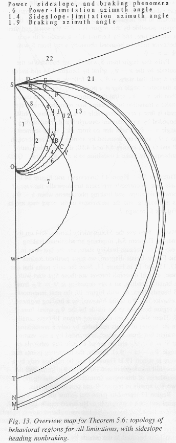
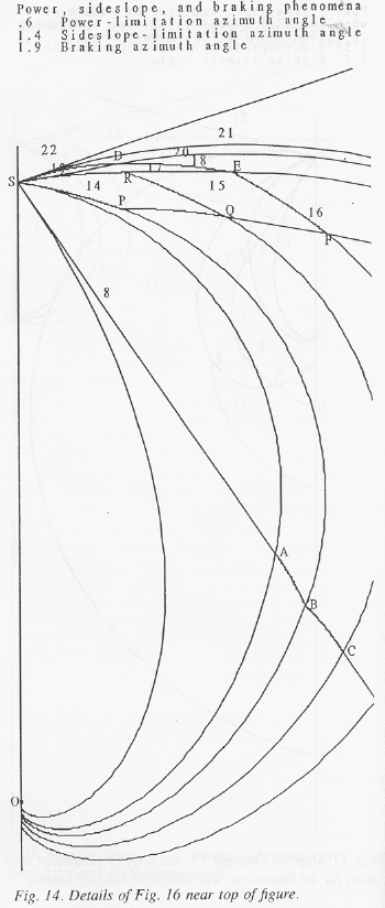
Region 17 represents paths that follow the ![]() �spiral and then a
straight line. But now region 17 is truncated because the line can only subtend
�spiral and then a
straight line. But now region 17 is truncated because the line can only subtend
![]() . By Lemma
4.7 the
. By Lemma
4.7 the ![]() �spiral
is the only additional behavior that can be added. This new region 18 is
bounded to the outside by a
�spiral
is the only additional behavior that can be added. This new region 18 is
bounded to the outside by a ![]() �spiral through a point D, and to the
inside by a
�spiral through a point D, and to the
inside by a ![]() �spiral
through a point E which is the intersection of the straight line from R
starting at
�spiral
through a point E which is the intersection of the straight line from R
starting at ![]() �and
the
�and
the ![]() �spiral
from D (the intersection of the circular arc for region 19 with its
accompanying straight line). Note the path from R to E is a straight line
because paths in region 17 must end in straight lines.
�spiral
from D (the intersection of the circular arc for region 19 with its
accompanying straight line). Note the path from R to E is a straight line
because paths in region 17 must end in straight lines.
Similarly, region 15 in Fig. 11 gets truncated and behavior
16 holds outside this. Similarly, the new region 16 is bounded to the outside
by the inner ![]() �spiral
of region 18, and to the inside by another
�spiral
of region 18, and to the inside by another ![]() �spiral through a new point F. F is the
intersection of the straight line from Q starting at
�spiral through a new point F. F is the
intersection of the straight line from Q starting at ![]() �with the
�with the ![]() �spiral from E. Finally, region
12 is truncated in a similar manner, and a new region 13 is created outside it
but inside the other regions defined by
�spiral from E. Finally, region
12 is truncated in a similar manner, and a new region 13 is created outside it
but inside the other regions defined by ![]() �spirals. The boundary between 12 and 13
is a circle arc like its neighbors.
�spirals. The boundary between 12 and 13
is a circle arc like its neighbors.
Now use the Monotonicity Lemma 4.13 to superimpose an
additional power restriction, in a manner analogous to the way the power
restriction was applied to Theorem 5.4 to get Theorem 5.5. Paths that start
with a ![]() �are
not affected. By Lemma 4.14, the outermost changed path's first behavior must
be a straight-line segment starting at
�are
not affected. By Lemma 4.14, the outermost changed path's first behavior must
be a straight-line segment starting at ![]() �intersecting the uphill sideslope circle
arc at some point A. It must then make a transition to a
�intersecting the uphill sideslope circle
arc at some point A. It must then make a transition to a ![]() �spiral, follow it for a maximum
distance of �
�spiral, follow it for a maximum
distance of �![]() �to
some point B, and then make a transition to a �
�to
some point B, and then make a transition to a �![]() �spiral for an angle
�spiral for an angle ![]() �again; these points of
intersection are with the circular arcs defined above. The next behavior is a
straight line from a point C to a point V, and then the only remaining behavior
is a
�again; these points of
intersection are with the circular arcs defined above. The next behavior is a
straight line from a point C to a point V, and then the only remaining behavior
is a ![]() �spiral
by Lemma 4.7. By Lemmas 4.9 and 4.10,
�spiral
by Lemma 4.7. By Lemmas 4.9 and 4.10, ![]() �spirals are formed to the inside of all these
intersection points (A, B, C, and V) as images under mapping of the
�spirals are formed to the inside of all these
intersection points (A, B, C, and V) as images under mapping of the ![]() �spiral from S. QED.
�spiral from S. QED.
To illustrate the effect of map rotation that occurs with
varying ![]() �and
�and ![]() , Fig. 15 shows the
same case as Fig. 12, but where
, Fig. 15 shows the
same case as Fig. 12, but where ![]() �and
�and ![]() �have been changed and hence
�have been changed and hence ![]() �to "stretch"
the phenomena in rotation about O.
�to "stretch"
the phenomena in rotation about O.
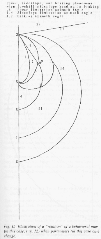
6. Cases of abrupt-turn impermissibility and inverted cones
The optimal paths we have developed can involve abrupt turns of two kind: from one critical-power heading to the other, and from an uphill critical-sideslope heading to a downhill critical-sideslope heading. These are reasonable for many vehicles because the power maximum is often only a steady-state maximum, and centrifugal force can prevent the overturn on sideslope turns. But this does not apply to all vehicles. The companion paper (Rowe and Kanayama 1992) analyzes this case it detail, and we show only an example of the behavioral map for the case in which all limitations apply and the sideslope heading is nonbraking (Fig. 16). Basically, two arrows are removed from the Fig. 1 state diagram, which removes ten possible state sequences from Fig. 7. This means for the first time that certain places on the cone cannot be reached from certain other places, the "unreachable" region in Fig. 16.
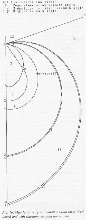
If the surface is reversed in height so the cone vertex becomes a minimum, we have an "inverted cone" where the gradient vector is exactly reversed from the terrain we have so far considered. Portions of inverted cones can model sinkholes and ravines. Optimal paths on inverted cones have many analogies to optimal paths on noninverted cones, with a few key differences, analyzed in the companion paper (Rowe and Kanayama 1992). Basically, all the arrows in the Fig. 1 state diagram can be proved to be reversed. We show only two examples of behavioral maps, for the two most complicated cases: all limitations where the sideslope heading is braking (Fig. 17), and all limitations where the sideslope heading is nonbraking (Fig. 18).
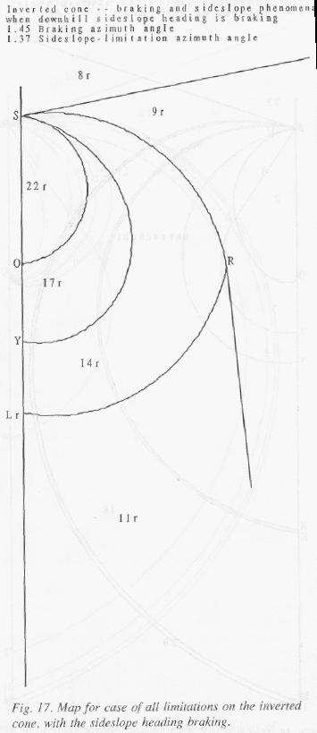
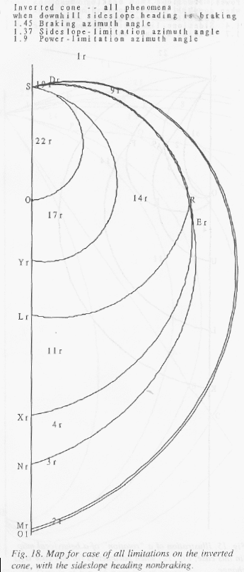
The case with both the above ideas together, no turns allowed on an inverted cone, turns out almost identical to the no-turns case on the noninverted cone.
7. Finding the exact optimal path to a point
Given a particular start point and goal point, it is
straightforward to find what behavioral region it is in from the behavioral
maps of Figs. 8-18. Standard algorithms for determining within what polygon a
point is located can be extended to handle curved region boundaries. To
minimize the number of comparisons of the point to boundary curves, a decision
tree (Pavlidis 1982) can be constructed based on the signs of simple formulae:
the sign of a formula of the form ax+by+c for lines, and the sign of a formula
of the form ![]() �for
spirals, where x and y are the Cartesian coordinates of the point and r and
�for
spirals, where x and y are the Cartesian coordinates of the point and r and ![]() �are the polar
coordinates. The depth of the decision tree is the ceiling on the logarithm of
the number of line and spiral segments. The most complicated Figure, Fig. 13,
has only 25 such segments, so the maximum tree depth is 5.
�are the polar
coordinates. The depth of the decision tree is the ceiling on the logarithm of
the number of line and spiral segments. The most complicated Figure, Fig. 13,
has only 25 such segments, so the maximum tree depth is 5.
Then given the optimal behavior between a particular start
point and a particular goal point, it is straightforward to find the actual
optimal path. If the optimal behavior is a single straight line it is trivial
to find, and if the optimal behavior is two spirals then the turn point can be
found by equating the parameterized equations of the two spirals. Otherwise
iteration is necessary to find the zero of the function which measures the
nearest approach of the path (negative for the uphill side, positive for the
downhill side) to the goal point. This is a well-behaved single-variable
optimization with no danger of secondary local optima since the function is
monotonic with respect to either the length of the first segment or the initial
�![]() �heading.
Thus it is similar to the optimization needed to find the path to a point when
the path must obey Snell's Law across a boundary between two weighted regions
(Rowe and Richbourg 1990). Newton's method or similar techniques can speed up
iteration since derivatives of the cost function are straightforward to
compute, being based on exponentials and trigonometric functions.
�heading.
Thus it is similar to the optimization needed to find the path to a point when
the path must obey Snell's Law across a boundary between two weighted regions
(Rowe and Richbourg 1990). Newton's method or similar techniques can speed up
iteration since derivatives of the cost function are straightforward to
compute, being based on exponentials and trigonometric functions.
8. A wavefront-propagation implementation for comparison
To partially confirm our theoretical analysis, we implemented a computer program to find approximately optimal paths on a cone by propagating costs between cells on a uniform grid, a frequently used technique also referred to as "wavefront propagation." Fig. 19 shows typical results, for the cases and parameters described in Figs. 13-14 except without power limitations. Fig. 19 shows paths found on a 41 by 41 grid with the cone vertex at the center. The height of the cone vertex was 20 units, and the elevations at the endpoints of the horizontal line running through the cone vertex were 16 units, giving a gradient inclination of 12.6 degrees. Paths were propagated in each of 32 possible directions at each cell. Costs were computed using the formulae given in Section 2 of this paper, using as the gradient for a segment of path the vector average of the gradient vectors at the two endpoints of the segment, with an artificial small cost proportional to path length for braking episodes to partially model the second optimality condition at the end of section 2.1. (The averaging of gradients accounts for some outright errors in Fig. 19 where some of the segments shown are not fully sideslope-permissible.) The starting point was a point vertically above the cone vertex, and the cone vertex is at the center of the figure.
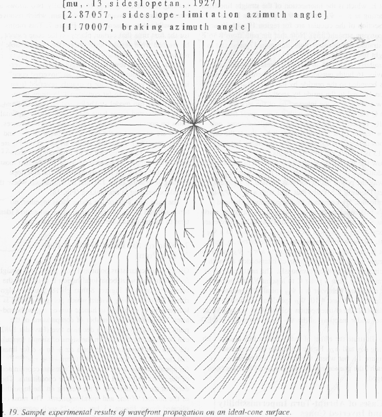
Fig. 20 provides comparison "propagations" about a start point using our methods discussed earlier, using Fig. 4 as a Markov state model. Comparing Fig. 19 with 20, path trends are similar but the wavefront propagation paths are considerably less elegant and subject to curious unnecessary complexities. Paths cross over one another in strange ways and make counterintuitive abrupt turns for no good reason. Although a 32-direction propagation should yield paths with an additional cost beyond the optimum of only sec(0.1)=1 = 0.5%, the counterintuitive nature of the paths makes them very hard for people to follow, and requires considerable space for robots to follow. Smoothing could be done, but could uncontrollably create unsafe paths or otherwise suboptimal paths. On the other hand, the straight lines and spirals that we have proved to be the only components of optimal paths on a cone are easy to follow. Straight lines just require aiming at a fixed point in the far distance, and spirals just require maintaining a constant angle with respect to the gradient direction. Thus paths found by our methods should be far superior in usability to paths found by grid-propagation methods.
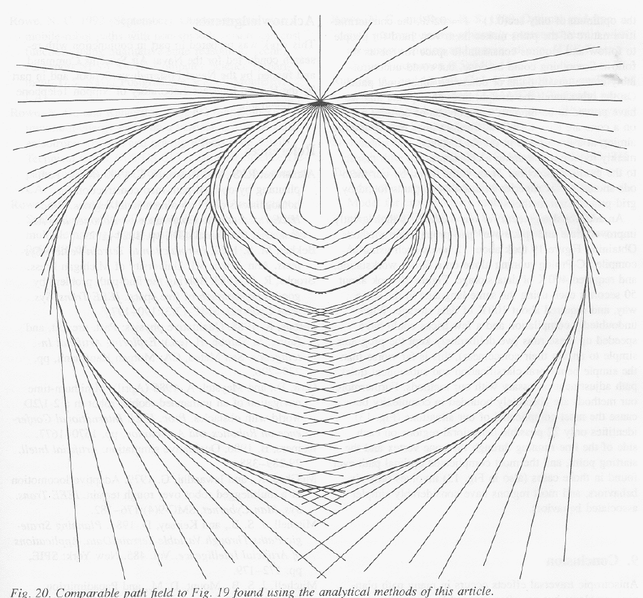
A further argument for our methods is their greatly improved time and space over grid-propagation methods. Obtaining Fig. 19 took about 12 hours each using uncompiled C-Prolog running alone on a Sun-3 workstation, and used 400K of data storage. Fig. 20 took about 50 seconds each using the same language in the same way, and used about 100K of data storage. While undoubtedly compilation and a few tricks could have speeded up these runs (we deliberately kept the programs simple to ensure their correctness), this is far worse than the simple behavioral classification and subsequent quick path adjustment necessary with our methods. Furthermore, our methods are absolutely bounded in complexity because the most complicated of our situations (Fig. 13) identifies only 22 possible behavioral regions on each side of the line running through the cone vertex and the starting point, and the most complicated optimal path ever found in those cases (also in Fig. 13) involves only 6 behaviors, and most regions have considerably simpler associated behaviors.
9. Conclusion
Anisotropic traversal effects occurs in many path-planning problems, but are often ignored by averaging them out. We have shown here that with proper analysis and a few reasonable physical idealizations, anisotropic path planning for minimum energy within 3.4% on traversal of terrain with slopes of 15 degrees or less need not be much more complicated than regular isotropic path planning, even if the anisotropism allows discontinuous changes in cost-per-distance with heading and zero-cost abrupt turns by a vehicle. An arbitrary surface can be modelled with cone patches, and paths propagated across the patches; the formulas we provide then quickly define how the paths curve. Reasoning in advance about qualitative states and state transitions was the key to facilitating this quick calculation. We believe that similar techniques can be used for other anisotropic path planning problems.
References
Alexander, R. S. and Rowe, N. C. 1990 (May). Path planning by optimal-path-map construction for homogeneous-cost two-dimensional regions. Proc. IEEE International Conference on Robotics and Automation, Cincinnati, OH, pp. 1924-1929.
Bekker, M. S. 1969. Introduction to terrain-vehicle systems. Ann Arbor, MI: University of Michigan Press.
Brooks, R. A. 1983. Solving the find-path problem by good representation of free space. IEEE Transactions on Systems, Man, and Cybernetics, SMC-13(3): 190-197.
Forbus, K. 1988. Qualitative physics: past, present, and future. Exploring artificial intelligence, ed. H. Shrobe. San Mateo, CA: Morgan Kaufmann, pp. 239-296.
Gaw, D. and Meystel, A. 1986 (April). Minimum-time navigation of an unmanned mobile robot in a 2-1/2D world with obstacles. Proc. IEEE International Conference on Robotics and Automation, pp. 1670-1677.
Kuipers, B. 1986. Qualitative simulation. Artificial intelligence 29: 289-388.
McGhee, R. and Iswandhi, G. 1979. Adaptive locomotion of a multilegged robot over rough terrain. IEEE Transactions on Systems, Man, and Cybernetics SMC-9(4): 176-182.
Mitchell, J. S. B. and Keirsey, D. 1984. Planning strategic paths through variable terrain data. Applications of Artificial Intelligence, volume 485. New York: SPIE, pp. 172-179.
Mitchell, J. S. B., Mount, D. M., and Papadimitriou, C. H. 1987. The discrete geodesic problem. SIAM Journal on Computing 16(4): 647-668.
Mitchell, J. S. B. and Papadimitriou, C. H. 1991. The weighted region problem: finding shortest paths through a weighted planar subdivision. Journal of the Assocation for Computing Machinery 38(1): 18-73.
Papadakis, N. A. and Perakis, A. N. 1990. Deterministic minimal time vessel routing. Operations Reserach 38(3): 426-438.
Parodi, A. M. 1985. Multi-goal real-time global path planning for an autonomous land vehicle using a high-speed graph search processor. Proc. IEEE International Conference on Robotics and Automation. New York: IEEE, pp. 161-167.
Pavlidis, T. 1982. Graphics and image processing. Rockville, MD: Computer Science Press.
Rowe, N. C. 1992 (September). Obtaining optimal mobile-robot paths with non-smooth anisotropic cost functions using qualitative-state reasoning. Technical report NPS-CS-012. Monterey, CA USA: Computer Science Department, U.S. Naval Postgraduate School.
Rowe, N. C. and Kanayama, Y. 1992 (September). Near-minimum-energy paths on a vertical-axis cone with anisotropic friction and gravity effects: the details. Technical report NPS-CS-013. Monterey, CA USA: Computer Science Department, U. S. Naval Postgraduate School.
Rowe, N. C. and Richbourg, R. F. 1990. An efficient Snell's-Law method for optimal-path planning across multiple homogeneous-cost regions. Int. J. Robotics Res. 9(6): 48-66.
Rowe, N. C. and Ross, R. S. 1990. Optimal grid-free path planning across arbitrarily-contoured terrain with anisotropic friction and gravity effects. IEEE Transactions on Robotics and Automation 6(5): 540-553.
Rula, A. A. and Nuttall, C. J. 1971 (July). An analysis of ground mobility models (ANAMOB). Technical Report M-71-4. Vicksburg, MS, USA: U.S. Army Corps of Engineers, Waterways Experiment Station.
Sharir, M. and Schorr, A. 1986. On shortest paths in polyhedral spaces. SIAM Journal of Computing 15(1): 193-215.
Turnage, G. W. and Smith, J. L. 1983 (September). Adaptation and condensation of Army Mobility Model for cross-country mobility mapping. Technical Report GL-83-12. Vicksurg, MS, USA: U. S. Army Corps of Engineers, Waterways Experiment Station.
Captions for Figures
Fig. 1:� State graph for optimal-traversal behaviors on a peak-maximum vertical-axis cone
Fig. 2:� Illustration for Lemma 4.1
Fig. 3:� Illustration for Lemma 4.4
Fig. 4:� Illustration for Lemma 4.7
Fig. 5:� Mathematical description of the points labeled in the cone-behavior maps of Figs. 8-18 (formulae can be scaled and shifted for arbitrary starting points).� The O1, O2, etc. points are not labeled in the Figures when they are quite close to the labeled "O"; they represent the intersections with the y-axis of the power spirals from points S, A, B, C, V, and H.
Fig. 6: Identification of the curve types in the cone maps (Figs. 8-18); all curve portions not mentioned above are straight-line segments.
Fig. 7: The 22 possible optimal-path types on a vertical-axis peak-maximum cone.� The type numbers are used in Figs. 8-18 to label each region; the "r" after a number in Figs. 17 and 18 indicates that the behavior list should be reversed.� This table (and the analysis of this paper) is written assuming the first behavior is clockwise with respect to the cone vertex, and there are 22 other corresponding path types for paths that start counterclockwise.
Fig. 8:� Map for Theorem 5.1: topology of behavioral regions for braking only
Fig. 9:� Map for Theorem 5.2: topology of behavioral regions for power limitations only
Fig. 10:� Map for Theorem 5.3: topology of behavioral regions for both braking and power limitations
Fig. 11:� Map for Theorem 5.4: topology of behavioral regions for sideslope limitations only
Fig. 12:� Map for Theorem 5.5: topology of behavioral regions for all limitations, with sideslope heading braking
Fig. 13:� Overview map for Theorem 5.6: topology of behavioral regions for all limitations, with sideslope heading nonbraking
Fig. 14:� Details of Fig. 16 near top of Figure
Fig. 15:� Illustration of a "rotation" of a
behavioral map (in this case, Fig. 12) when parameters (in this case ![]() ) change
) change
Fig. 16:� Map for case of all limitations with turns disallowed and with sideslope heading nonbraking
Fig. 17: Map for case of all limitations on the inverted cone, with the sideslope heading braking
Fig. 18: Map for case of all limitations on the inverted cone, with the sideslope heading nonbraking
Fig. 19:� Sample experimental results of wavefront propagation on an ideal-cone surface
Fig. 20:� Comparable path field to Fig. 19 found using the analytical methods of this paper