Obtaining Optimal Mobile-Robot Paths with Non-Smooth Anisotropic Cost Functions Using Qualitative-State Reasoning
Neil C. Rowe
Code CS/Rp, Department of Computer Science
Naval Postgraduate School Monterey, CA USA 93943 ncrowe at nps.navy.mil
Abstract
Realistic path-planning problems frequently show anisotropism, dependency of traversal cost or feasibility on the traversal heading. Gravity, friction, visibility, and safety are often anisotropic for mobile robots. Anisotropism often differs qualitatively with heading, as when a vehicle has insufficient power to go uphill or must brake to avoid accelerating downhill. Modeling qualitative distinctions requires discontinuities in either the cost-per-traversal-distance function or its derivatives, preventing direct application of most results of the calculus of variations. We present a new approach to optimal anisotropic path planning that first identifies qualitative states and permissible transitions between them. If the qualitative states are chosen appropriately, our approach replaces an optimization problem with such discontinuities by a set of subproblems without discontinuities, subproblems for which optimization is likely to be faster and less troublesome. Then the state space in the near neighborhood of any particular state can be partitioned into "behavioral regions" representing states optimally reachable by single qualitative "behaviors", sequences of qualitative states in a finite-state diagram. Simplification of inequalities and other methods can find the behavioral regions. Our ideas solve problems not easily solvable any other way, especially those with what we define as "turn-hostile" anisotropism. We illustrate our methods on two examples, navigation on an arbitrarily curved surface with gravity and friction effects (for which we show much better performance than a previously-published program 22 times longer), and flight of a simple missile.
This work was supported in part by the U.S. Army Combat Developments Experimentation Center under MIPR ATEC 88-86. This work was also prepared in part in conjunction with research conducted for the Naval Air Systems Command and funded by the Naval Postgraduate School. This paper appeared in the International Journal of Robotics Research, 16, 3 (June 1997), 375-399. The equations were reconstructed in 2007 for better readability.
1. Introduction
Suppose you want to send a robot submarine upriver against a current. Is it better to head straight upriver, or zigzag? If both are feasible for the vehicle, the question is hard to answer because there are so many different headings and segment lengths that could be used in zigzagging. The minimum-energy path might be to head 10 meters at 53 degrees clockwise of upcurrent, then 10 meters at 53 degrees counterclockwise of upcurrent, and so on; the extra length of such a path might be compensated for by the decreased energy needed to fight the current at those headings. Path-planning researchers have often intuitively dismissed such paths, but we would like to provide a theoretical basis. After all, switchbacks are common on mountain roads.
The issue is anisotropism, dependency of traversal difficulty or cost-per-distance on the direction of traversal at a point. Path planners are often confronted with natural domains exhibiting anisotropism; for mobile agents including robots, the most frequent causes are gravity and friction. Work against gravity adds cost for uphill traversal and subtracts cost for downhill traversal; friction works opposite the agent's motion. Winds and currents can also act in a consistent direction, as in the ocean-travel work of [Papadakis and Perakis 1990]. Anisotropic phenomena may also reflect directional danger, as when travel is safer if a landmark is kept in front. Anisotropic phenomena can also arise from agent limitations such as maximum power (vehicles cannot climb an incline of more than a certain steepness) and overturn danger (vehicles perpendicular to a slope gradient can roll over). (These should not be confused with dexterity anisotropism for stationary manipulators [Klein and Miklos 1991].) Of course, there are other equally-important issues in path planning such as obstacle avoidance and handling of isotropic varying costs, which we will ignore here.
Unfortunately, standard path-planning methods based on "wavefront propagation" across a uniform grid of cells do not work as well for anisotropic problems as for isotropic problems, though they have been tried as in [Gaw and Meystel 1986] and [Parodi 1985]. The disadvantages of such methods are discussed in [Rowe and Ross 1990] and [Mitchell and Keirsey 1984], and the primary disadvantage is that wavefront-propagation methods round all headings to a fixed set, which can considerably distort path geometry from the optimal one. For instance, our experiments in finding minimum-energy paths on the surface of a vertical-axis cone [Rowe and Kanayama 1994] using a 32-direction wavefront propagation gave different and far more complex solution paths than the true optimal paths proved by theoretical analysis. Furthermore, smoothing the wavefront-propagation paths did not help much, because the true optimal paths had subtle abrupt changes in curvature that are hard to approximate. Wavefront propagation has particular trouble in modeling ranges of impermissible headings, since to be safe these ranges must be widened to a range of headings used in the propagation; this may eliminate optimal paths that follow borderline-impermissible headings for a distance, which were common solutions in [Rowe and Kanayama 1994]. With the analysis we present in this paper, ray-tracing methods can get solutions arbitrarily close to optimal for anisotropic problems, as we will discuss in section 5.2.
The calculus of variations can find optimal paths for many anisotropic-cost problems, as dependence of cost-per-distance on heading is equivalent to dependence of cost-per-distance on the first derivatives of the path parameterization. However, classic results such as the Euler differential equation assume continuity of some or all derivatives of the cost-per-distance function. Power-maximum, stability, and braking considerations on moving agents violate this; especially troublesome is the possibility of zero-cost abrupt turns in many high-level vehicle models. To successfully apply variational methods then, it is necessary to find subspaces of the state space within which continuity of cost-per-distance and its derivatives is assured. [Rowe and Richbourg 1990] did this for the isotropic "weighted-region problem" where subspaces correspond to physical areas. Unfortunately, the subspaces for anisotropic phenomena are trickier to formulate than those for the weighted-region problem, because of the zero-cost abrupt state changes, and we will be forced back to more basic mathematical considerations before we can ascertain the form of optimal solution paths.
So this paper will attack anisotropic problems by identifying "qualitative states" that partition the space of possible headings at a point in particularly nice ways. Qualitative states for continuous-valued problems have been exploited in the field of qualitative physics [Forbus 1988; Kuipers 1986] for preliminary analysis of physics problems. For anisotropic path planning, each qualitative state can characterize a piece of an optimal path, and the pieces can be assembled into complete paths by studying possible state sequences of a finite-state machine. ([Liu and Daneshmend, 1991] and [Holmes and Jungert, 1988] use this idea for isotropic obstacle-avoidance path planning.) Then for a particular start state, the optimal path to a goal can be found by a well-behaved optimization local to a state sequence. Not all anisotropisms can be so handled, however, so we will provide a key theorem defining those that can.
2. Two examples of anisotropic path planning used in this paper
2.1. A surface traversal model with gravity and friction effects
Consider a vehicle subject to gravity and friction effects, traveling on a smooth sloped surface. Examples are army vehicles like tanks and personnel carriers traveling overland. The amount of energy that the vehicle requires for constant-speed travel from a particular place on the surface is a function of direction. If the surface is sufficiently steep, there will be a range of uphill directions too steep to permit the vehicle to have constant-speed travel. That is, the vehicle will slow and come to a stop if it attempts to travel in those directions.
Similarly, if a surface is sufficiently steep and the vehicle is traveling downhill, the vehicle must brake to prevent accelerating to an unsafe speed. For such braking, the vehicle need not provide any power (beyond that to idle the motor, which we assume is negligible).
Finally, if the vehicle is like most vehicles, and the surface is sufficiently steep, there is a range of "sideslope" or cross-slope directions that the vehicle cannot negotiate without overturning on its side. That is, then the projection of the vehicle's center of gravity will fall outside the polygon of its support points. There are two such heading ranges, one clockwise of uphill, one counterclockwise.
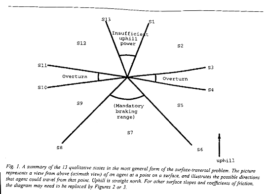
Fig. 1 illustrates these ideas. It represents a view from above of azimuth
directions of traversal from the center of the figure, with uphill north on the
page. Uphill headings between the rays labeled S1 and S13 have insufficient
power to maintain constant speed. Downhill headings between S6 and S8 require
braking to maintain constant speed. Sideslope headings between S3 and S4 or
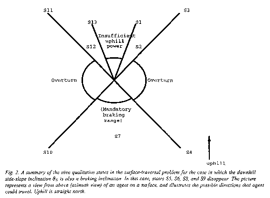
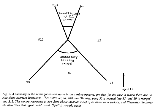
between S10 and S11 run the risk of overturn. Fig. 1 shows the most complex
case, while Figs. 2 and 3 illustrate other possibilities when some of the
ranges coalesce. It is clear we will not be able to model energy cost of
constant-speed traversal as a continuous-derivative function of direction, and
thus must be careful in applying mathematics to finding optimal paths on such
surfaces.
Appendix A provides a formal statement of this model.
2.2. A missile dynamics model
As an example of three-dimensional path planning, consider a missile. While some work on optimal isotropic three-dimensional path planning has been done [Sharir and Schorr 1986; Mitchell et al 1987] little attention has been paid to anisotropic three-dimensional problems. Assume we have a missile that will be "fired" or set in motion at a fixed point but can be turned to any orientation before firing. Assume there are limits on how quickly the missile can curve in the azimuth direction, and independent limits on how steep a climb or dive it can negotiate. Fig. 4 shows some sample missile paths from a starting point.
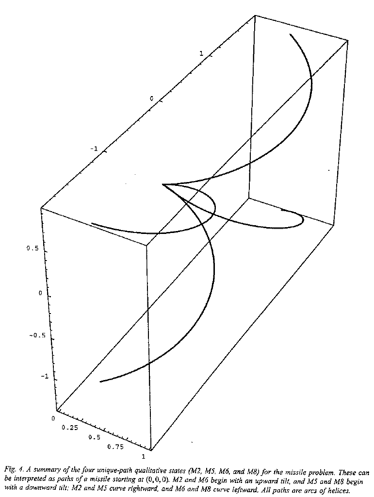
If the missile climbs as fast as it can, we will call its behavior either M1, M2, or M6. If it curves to the left as tightly as it can, that is M2 behavior; if it curves to the right as tightly as it can, that is M6; else it is M1. If the missile dives as fast as it can, we will call its behavior either M4, M5, or M8. If it curves to the left as tightly as it can, that is M5 behavior; if it curves to the right as tightly as it can, that is M8; else it is M4. Paths for M2, M6, M5, and M8 are shown explicitly in Fig. 4; they are all helices.
Otherwise, the climbing or diving of the missile must be between the two extremes, and we will call its behavior either M3, M7, or M9. If it curves to the left as tightly as it can, that is M3 behavior; if it curves to the right as tightly as it can, that is M7; else it is M9. In Fig. 4, M2, M5, M6, and M8 can be thought of as the corners of a curved "window" representing all places that can be reached by a missile traveling a fixed azimuth distance. M1 forms the top of the window, M4 the bottom, M3 the left side, and M7 the right side. Any paths strictly inside the window are M9.
Appendix B provides a formal statement of this model.
3. General results about qualitative states and optimal state transitions
Although qualitative states can be identified along non-optimal paths, optimality considerations strongly constrain what the states mean and what sort of transitions are possible between them. Hence we consider conditions on optimal state sequences.
3.1. Turn-hostile cost-per-distance functions
Since we seek vehicle paths, it is fair to exclude certain pathological
kinds of paths from consideration. Following [Kuipers 1986], we will only
consider optimal paths composed of a finite number of segments, where each
segment has Cartesian coordinates that are smooth functions of arclength. This
means that a path must contain only a finite number of discontinuities in any
of its derivatives of its parameterized coordinates; we shall call such paths reasonable
paths. We give a key lemma about optimal reasonable paths. It applies to a
given cost-per-distance function ![]() ; intuitively,
; intuitively, ![]() is the shape of an equicost
wavefront propagating about a point within its near neighborhood.
is the shape of an equicost
wavefront propagating about a point within its near neighborhood.
Lemma 3.1 (Shortcut Suboptimality Condition: Suppose the anisotropic
cost-per-distance function c(g )
near a point P is a function of only the azimuth (g=j
) heading in two or three dimensions, or of only the inclination heading (g = q
) in three dimensions, and has continuous derivatives with respect to headings
within some range R of path direction representing positively-weighted vector
averages between two fixed directions ![]() and
and ![]() . Then an optimal reasonable path cannot
turn from
. Then an optimal reasonable path cannot
turn from ![]() to
to
![]() at P
unless every direction in R is higher in cost-per-distance than min(
at P
unless every direction in R is higher in cost-per-distance than min(![]() ,
,![]() ). Proof: Since a
reasonable path can only have a finite number of discontinuities in heading or
heading derivatives, a Taylor series approximation of the path at P can model
the path before and after the turn as two line segments in the limit. By
geometry, any direction in R corresponds to a feasible "shortcut" between
the two line segments and infinitesimally close to P. This shortcut will be a
shorter route between the two segments, and it must be a permissible travel
direction if the cost-per-distance function is continuous at P for direction
range R. So if the turn is optimal, every possible such shortcut must have a
greater cost-per-distance than either c(
). Proof: Since a
reasonable path can only have a finite number of discontinuities in heading or
heading derivatives, a Taylor series approximation of the path at P can model
the path before and after the turn as two line segments in the limit. By
geometry, any direction in R corresponds to a feasible "shortcut" between
the two line segments and infinitesimally close to P. This shortcut will be a
shorter route between the two segments, and it must be a permissible travel
direction if the cost-per-distance function is continuous at P for direction
range R. So if the turn is optimal, every possible such shortcut must have a
greater cost-per-distance than either c(![]() ) or c(
) or c(![]() ).. QED.
).. QED.
Lemma 3.1 is hard to apply. But suppose a vehicle tried to save energy going
uphill by zigzagging or slaloming, first at an azimuth heading 45 degrees right
of uphill, then an equal distance 45 degrees left of uphill. Using the
mathematical model in Appendix A for a surface of inclination 0.2 radians with
coefficient of friction 0.15, we would experience a cost-per-distance 83% of
that incurred by heading straight uphill by heading 45 degrees of uphill, but
we would make only 71% of the uphill progress per unit distance, a bad bargain.
Similarly if we head 60 degrees of uphill, cost-per-distance is 71% of that
incurred straight uphill, but uphill progress is 50%. So it appears that
zigzagging uphill is not desirable with this cost-per-distance function. Can we
generalize this? To be more formal, define cost-per-distance ![]() of some heading g at point P in some plane L as turn-hostile
in some open interval of heading (
of some heading g at point P in some plane L as turn-hostile
in some open interval of heading (![]() ,
, ![]() ) in L if the function and all
its derivatives are continuous within that range and no reasonable optimal path
need make an abrupt turn at P between two headings in that range. Intuitively,
turn-hostility says that optimal paths cannot zigzag.
) in L if the function and all
its derivatives are continuous within that range and no reasonable optimal path
need make an abrupt turn at P between two headings in that range. Intuitively,
turn-hostility says that optimal paths cannot zigzag.
Theorem 3.1: Suppose the cost-per-distance for a traversal at point P
within plane L is c(g) where g is the traversal heading in L.
Suppose c(g), c'(g), and c''(g) are continuous on an open interval ![]() of g in L, where
of g in L, where ![]() . A sufficient condition
for c(g) at P to be turn-hostile
in R for L is that
. A sufficient condition
for c(g) at P to be turn-hostile
in R for L is that ![]() where
where
![]() for
all b in the range
for
all b in the range ![]() . Proof:
See Fig. 5; this shows a path from A to B that is making an abrupt left turn at
point P, and a simple straight shortcut across it from A to B. The heading
range from
. Proof:
See Fig. 5; this shows a path from A to B that is making an abrupt left turn at
point P, and a simple straight shortcut across it from A to B. The heading
range from ![]() clockwise
to
clockwise
to ![]() represents
the allowable shortcut headings that we will consider. We must determine the
conditions when a "detour" path like APB costs less than any straight
"shortcut" like AB infinitesimally close to P, where the shortcut
heading is g in L,
represents
the allowable shortcut headings that we will consider. We must determine the
conditions when a "detour" path like APB costs less than any straight
"shortcut" like AB infinitesimally close to P, where the shortcut
heading is g in L, ![]() , using Lemma 3.1.
, using Lemma 3.1.
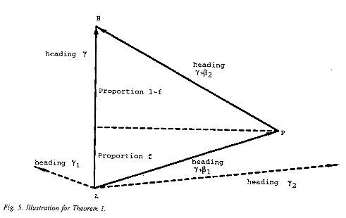
Let the headings of the detour be ![]() and
and ![]() , with
, with ![]() and
and ![]() opposite signs. Let the projection
of the first detour segment onto the shortcut be fraction f of the total
distance of the shortcut. Then computing the costs, we wish to know when
opposite signs. Let the projection
of the first detour segment onto the shortcut be fraction f of the total
distance of the shortcut. Then computing the costs, we wish to know when ![]() with the side
condition
with the side
condition ![]() (which
says the AP and PB must deviate the same distance from the line segment AB).
For the shortcut to be optimal, by Lemma 3.1, the inequality must hold for
every
(which
says the AP and PB must deviate the same distance from the line segment AB).
For the shortcut to be optimal, by Lemma 3.1, the inequality must hold for
every ![]() and
and
![]() in the
given range. By substituting
in the
given range. By substituting ![]() we see that it is sufficient to
prove the concavity of
we see that it is sufficient to
prove the concavity of ![]() on the range
on the range ![]() when g is held constant, for an arbitrary g. This is since if h ( x ) is concave then
when g is held constant, for an arbitrary g. This is since if h ( x ) is concave then ![]() where 0 < f
< 1; and the condition that
where 0 < f
< 1; and the condition that ![]() requires the secants of
requires the secants of ![]() and
and ![]() to be positive,
and hence 0 < f < 1.
to be positive,
and hence 0 < f < 1.
Now concavity of ![]() is proved if the second partial
derivative of this with respect to t is positive. This is
is proved if the second partial
derivative of this with respect to t is positive. This is ![]() , which is positive if and only
if the expression in brackets is positive, or
, which is positive if and only
if the expression in brackets is positive, or ![]() . But we would like that in terms of b, so
. But we would like that in terms of b, so ![]() which is
which is ![]() . Substituting this in
. Substituting this in ![]() , we get the
criterion
, we get the
criterion ![]() .
QED.
.
QED.
Theorem 3.1 is important because it says that at particular places on
particular surfaces with anisotropic cost-per-distance functions that obey the
relatively simple criterion ![]() , optimal paths cannot turn while
they stay within particular heading ranges. Maximal such ranges in which the
Theorem holds correspond to the qualitative states introduced in Section 2. A
Corollary extends the idea of turn-hostility to prohibit curving of optimal
paths in homogeneous regions of planes under certain conditions.
, optimal paths cannot turn while
they stay within particular heading ranges. Maximal such ranges in which the
Theorem holds correspond to the qualitative states introduced in Section 2. A
Corollary extends the idea of turn-hostility to prohibit curving of optimal
paths in homogeneous regions of planes under certain conditions.
Corollary 3.1: Suppose the cost-per-distance for a traversal in a region
S within plane L is ![]() where
g is some heading defining
the direction in L and S (so c is independent of position in S). Suppose
where
g is some heading defining
the direction in L and S (so c is independent of position in S). Suppose ![]() ,
, ![]() , and
, and ![]() are continuous on
an open interval
are continuous on
an open interval ![]() of
g in S on L, where
of
g in S on L, where ![]() . Suppose
. Suppose ![]() at P is turn-hostile
in R for S and L. Then an optimal path segment in S and L whose headings are
exclusively in R must be a straight line segment, and cannot be curved.
Proof: Recursively subdivide the path and apply Theorem 3.1 to the pieces. QED.
at P is turn-hostile
in R for S and L. Then an optimal path segment in S and L whose headings are
exclusively in R must be a straight line segment, and cannot be curved.
Proof: Recursively subdivide the path and apply Theorem 3.1 to the pieces. QED.
Both Theorem 3.1 and Corollary 3.1 refer to heading ranges of less than 90 degrees to avoid considering possible detours where AP or PB in Fig. 5 is longer than AB. Such detours are almost never desirable, and the two applications of this paper rarely needed them during experiments. But if necessary, additional artificial landmark values (partitioning headings) can subdivide qualitative states.
3.2. Four applications of Theorem 3.1
Hence a nonnegative isotropic cost-per-distance function is turn-hostile, since its derivatives with respect to heading are zero. The simplified surface-navigation cost-per-distance function of Appendix A is isotropic on the contiguous nonbraking ranges in states S2, S5, S9, and S12, so those states must have turn-hostile optimal paths for path segments whose headings lie entirely within one of their ranges. By Corollary 3.1, optimal paths must be straight-line segments in these states. As for state S7, its paths are also turn-hostile, but this can be proved more easily without Theorem 3.1: Braking cost is proportional to elevation change, and between any two points there is a fixed total elevation change along any path, so there is never any need to turn on an all-braking feasible path to obtain lower cost. Hence optimal paths in S7 must also be straight-line segments.
As for the unsimplified surface-navigation model in Appendix A, we can now
show it has the same set of state transitions as were shown for the simplified
model in [Rowe and Ross 1990] and [Rowe and Kanayama 1994], on surfaces up to a
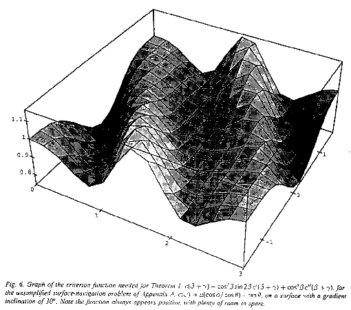
60 degree inclination angle. We can do this by graphing the criterion function
for Theorem 3.1 (the left side of the inequality for the main case) for the
range of possible g and b, and showing that it never goes negative;
the Theorem then guarantees turn-hostility of the cost-per-distance function.
Fig. 6 shows this surface for a gradient inclination of 30 degrees; the
left-right axis is g, and the
foreground-background axis is b.
Turn-hostile behavior holds up to about 60 degrees; the limit is not significant,
since few vehicles can navigate such very steep slopes.
Since sines and cosines cannot exceed 1, a simpler sufficient condition than
Theorem 3.1 is that ![]() and
and ![]() , since then:
, since then:

This simpler condition applies to the missile model of Appendix B. Missiles
generally try to go as fast as possible and are approximately confined to a
maximum climb inclination ![]() of 20% and a maximum dive
inclination
of 20% and a maximum dive
inclination ![]() of
10%, hence
of
10%, hence ![]() and
and
![]() both
must be less than
both
must be less than ![]() .
Within this heading range, [Wrenn 1989] fit a cubic formula for the energy
expenditure per unit time necessary for a cruise missile to maintain constant
speed, a usual constraint, of
.
Within this heading range, [Wrenn 1989] fit a cubic formula for the energy
expenditure per unit time necessary for a cruise missile to maintain constant
speed, a usual constraint, of ![]() where t is the tangent of the
inclination angle. The second term represents work against gravity, and its
integral is fixed between any two specified endpoints, so we can ignore it.
Hence we can use
where t is the tangent of the
inclination angle. The second term represents work against gravity, and its
integral is fixed between any two specified endpoints, so we can ignore it.
Hence we can use ![]() ,
where
,
where ![]() is
the inclination in radians. So
is
the inclination in radians. So ![]() and
and ![]() ; and clearly
; and clearly ![]() and
and ![]() . So the simpler sufficient
condition than Theorem 3.1 holds, and hence paths must be turn-hostile in
inclination
. So the simpler sufficient
condition than Theorem 3.1 holds, and hence paths must be turn-hostile in
inclination ![]() in
states M3 and M7, for inclinations between
in
states M3 and M7, for inclinations between ![]() and
and ![]() where the azimuth-turn rate is held
constant. Hence the optimal paths in M3 and M7 must be helices with a vertical
axis.
where the azimuth-turn rate is held
constant. Hence the optimal paths in M3 and M7 must be helices with a vertical
axis.
Transparent calcite crystals illustrate the consequences of inability of an anisotropism to qualify for Theorem 3.1. These crystals show sufficient anisotropism in the speed of light that two local minima of paths between a start and goal point occur, causing double images of objects viewed through them.
3.3. Inference of turn-hostility for composite cost-per-distance functions
Corollary 3.2: Suppose given cost-per-distance functions ![]() and
and ![]() are turn-hostile
within the same range, a range whose extent is less than
are turn-hostile
within the same range, a range whose extent is less than ![]() . Then
. Then ![]() is also turn-hostile in
that same range if
is also turn-hostile in
that same range if ![]() and
and
![]() are
positive. Proof: Derivatives are linear operators, so the criterion
function for the composite is the weighted sum of the criterion functions of
the component functions, each of which is positive or nonnegative, so the
result is positive. QED.
are
positive. Proof: Derivatives are linear operators, so the criterion
function for the composite is the weighted sum of the criterion functions of
the component functions, each of which is positive or nonnegative, so the
result is positive. QED.
For instance, consider adding a cost factor due to wind resistance to the surface-navigation problem in a nonbraking heading range. Since we just showed that the original problem was turn-hostile, if the wind-direction cost-per-distance by itself is turn-hostile, the composite function is turn-hostile.
Corollary 3.3: Suppose cost-per-distance functions ![]() and
and ![]() are turn-hostile within
the same range, a range whose extent is less than
are turn-hostile within
the same range, a range whose extent is less than ![]() . Then
. Then ![]() is also turn-hostile in that same
range if k > 0 and
is also turn-hostile in that same
range if k > 0 and ![]() , for all β such that
, for all β such that ![]() lies in the
range. Proof: The criterion function for the composite can be written as:
lies in the
range. Proof: The criterion function for the composite can be written as:

The first two lines each represent the product of three positive numbers. QED.
3.4. Transitions between two turn-hostile heading ranges
Theorem 3.2: Suppose a given cost-per-distance function ![]() is turn-hostile
on
is turn-hostile
on ![]() . Suppose
. Suppose
![]() is identical
to
is identical
to![]() except within
some interior subrange
except within
some interior subrange![]() so
so ![]() . Then no optimal path can turn from the
subrange
. Then no optimal path can turn from the
subrange ![]() to
the subrange
to
the subrange ![]() or
vice versa. Proof: Suppose such a turn goes from
or
vice versa. Proof: Suppose such a turn goes from ![]() to
to ![]() . Since
. Since ![]() is an open interval,
there must exist headings between
is an open interval,
there must exist headings between ![]() and
and ![]() that would shortcut the turn
infinitesimally close to the turn point. But this would violate the assumed
turn-hostility of
that would shortcut the turn
infinitesimally close to the turn point. But this would violate the assumed
turn-hostility of ![]() since
since
![]() ,
, ![]() , and this shortcut
heading would all lie in the original range
, and this shortcut
heading would all lie in the original range ![]() . QED.
. QED.
Theorem 3.2 applies over a range of heading (like between S3 and S4 in Fig.
1) that occurs within an otherwise simple-to-analyze range of heading. Note it
does not exclude possibly optimal turns from ![]() to
to ![]() , like S3-S4, to be discussed in section
3.7. We need two more theorems for similar cases, whose similar proofs are
omitted here to save space but are given in [Rowe, 1992].
, like S3-S4, to be discussed in section
3.7. We need two more theorems for similar cases, whose similar proofs are
omitted here to save space but are given in [Rowe, 1992].
Theorem 3.3: Suppose cost-per-distance function ![]() is turn-hostile on
is turn-hostile on ![]() . Suppose
. Suppose ![]() can be created
from
can be created
from ![]() by
increasing the cost-per-distance within some subrange
by
increasing the cost-per-distance within some subrange ![]() where
where![]() . Then no optimal path turns
from the subrange
. Then no optimal path turns
from the subrange ![]() to
the subrange
to
the subrange ![]() or
vice versa.
or
vice versa.
Theorem 3.4: Suppose cost-per-distance function ![]() is turn-hostile on
is turn-hostile on ![]() . Suppose
. Suppose ![]() can be created
from
can be created
from ![]() by
increasing the cost-per-distance within some subrange
by
increasing the cost-per-distance within some subrange ![]() where
where ![]() . Then no optimal
path turns from the subrange
. Then no optimal
path turns from the subrange ![]() to the subrange
to the subrange ![]() or vice versa.
or vice versa.
Theorems 3.2-3.4 rule out all transitions between surface-navigation states S2, S5, S9, and S12 on optimal paths. They rule out the transitions between S5 and S7 and between S9 and S7, since braking traversal (a cost-per-distance of zero) actually costs more than the formula for nonbraking cost-per-distance in the same heading range. Theorem 3.3 or 3.4 followed by Theorem 3.2 together rule out transitions between S2 and S7 and between S12 and S7.
3.5. Differential equations for critical qualitative states
Some qualitative states are so restrictive that they have only one possible heading at any point in space. We call such states critical states with respect to a particular vehicle model and class of headings. In the surface-navigation model, S1, S3, S4, S6, S8, S10, S11, and S13 are critical states. Paths by which a vehicle can remain in a particular critical state while traveling forward we shall call generalized contours, to broaden the usual meaning of contour beyond that of a curve perpendicular to uphill.
Let us consider generalized contours for surface traversal in more detail.
As discussed in Appendix A, it is sufficient to consider the projection of
paths from the surface to an azimuth plane. Let z(x ,y) be the elevation on the
surface; let ![]() be
a general name for either
be
a general name for either ![]() , -
, -![]() ,
, ![]() , or -
, or -![]() , the critical inclinations for the two
power-limitation and two critical-braking phenomena respectively. Then for the
inclination
, the critical inclinations for the two
power-limitation and two critical-braking phenomena respectively. Then for the
inclination ![]() at
a point on the surface for a path whose azimuth projection is y(x), we use the
first formula of Appendix A to get:
at
a point on the surface for a path whose azimuth projection is y(x), we use the
first formula of Appendix A to get:
After algebra, this gives the differential equation for the azimuth projection of path segments in qualitative states S1, S13, S6, and S8:
Since z is known, this is an ordinary first-order
differential equation. The interior of the square root requires that the
gradient magnitude be greater than the critical inclination. There are always
at least two solutions to the differential equation because of the ![]() : one for paths
curving clockwise of uphill (S1 and S6), and one for counterclockwise (S13 and
S8). The differential equation is solvable in closed form in special cases, as
when z is independent of y where
: one for paths
curving clockwise of uphill (S1 and S6), and one for counterclockwise (S13 and
S8). The differential equation is solvable in closed form in special cases, as
when z is independent of y where ![]() .
.
For the sideslope-stability contours, the important surface inclination is
perpendicular to the path direction. Since![]() , we get (qualitative states S3, S4, S10,
and S11):
, we get (qualitative states S3, S4, S10,
and S11):
If z is independent of y, this becomes ![]() .
.
As an example, consider the surface of an ideal cylinder with a horizontal
axis along the y-axis and with a unit radius. Such a cylinder could model a
ridge in real-world terrain. The top of the cylinder is a region of
sufficiently shallow slope that no generalized contours penetrate it, but
restrictions become increasingly significant in heading down the side of the
cylinder. Using the above, the generalized contours for power limitations are ![]() , and the critical-braking
contours are identical except for the substitution of
, and the critical-braking
contours are identical except for the substitution of ![]() for
for ![]() . The sideslope contours are
defined by
. The sideslope contours are
defined by ![]() .
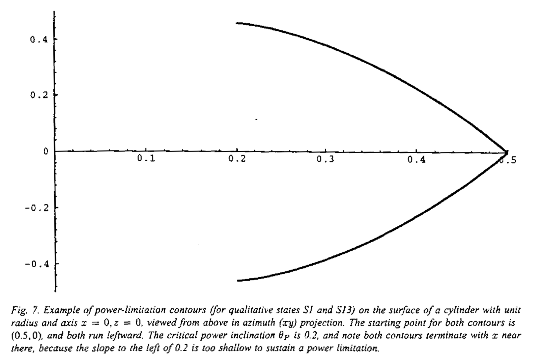
As an illustration, Fig. 7 shows the S1 and S13 power-limitation contours seen
in azimuth projection for traversal from the point (0.5,0), where the
projection of the axis of the cylinder is the line x = 0. Note that S1
and S13 tend increasingly uphill (to the left) as the slope decreases, and
finally stop at x = 0.2 when power limitations disappear. But the sideslope
contours on a cylinder can continue forever.
.
As an illustration, Fig. 7 shows the S1 and S13 power-limitation contours seen
in azimuth projection for traversal from the point (0.5,0), where the
projection of the axis of the cylinder is the line x = 0. Note that S1
and S13 tend increasingly uphill (to the left) as the slope decreases, and
finally stop at x = 0.2 when power limitations disappear. But the sideslope
contours on a cylinder can continue forever.
For the missile problem of Appendix B, states M2, M5, M6, and M8 are the critical states. Each has a unique associated three-dimensional path since their starting point, inclinations, and turn radius are fixed; these conditions result in helices whose axis is vertical. States M1, M3, M4, and M7 are critical with respect to either inclination or turn radius, what we can call "semi-critical"; they can be treated as critical states for the state subspace in which the noncritical heading is held constant.
3.6. Transitions between critical and noncritical states on optimal paths
Optimal paths may require transitions from the critical states of the last section to noncritical states. Many such transitions are ruled out by the following theorem and corollary.
Theorem 3.5: Suppose no turn is optimal at a point P from
noncritical-heading state N1 to noncritical-heading state N2 (with both heading
ranges interpreted on open intervals, as in Theorem 3.1). Suppose C is a
critical state adjacent to N1 (that is, its heading ![]() adjoins the open interval
of headings for N1) such that (1) the cost-per-distance for C is continuous
with the cost-per-distance in the heading range of N1, and (2) a turn from C to
N2 would cross part or all of the heading range of N1. Then no turn from C to
N2 is necessary on any optimal path through P. Proof: Such a turn could be
shortcut by a segment with a heading
adjoins the open interval
of headings for N1) such that (1) the cost-per-distance for C is continuous
with the cost-per-distance in the heading range of N1, and (2) a turn from C to
N2 would cross part or all of the heading range of N1. Then no turn from C to
N2 is necessary on any optimal path through P. Proof: Such a turn could be
shortcut by a segment with a heading ![]() infinitesimally close to
infinitesimally close to ![]() but in the
heading range of N1. Since
but in the
heading range of N1. Since ![]() is in the range of N1 and no turn
is optimal from N1 to N2, a turn from
is in the range of N1 and no turn
is optimal from N1 to N2, a turn from ![]() to N2 cannot be optimal. Therefore
a turn from
to N2 cannot be optimal. Therefore
a turn from![]() to N2 could not be more than infinitesimally better than a non-optimal turn,
and hence cannot, in the limit, be necessary for an optimal path. (N1 and N2
need not be adjacent.) QED.
to N2 could not be more than infinitesimally better than a non-optimal turn,
and hence cannot, in the limit, be necessary for an optimal path. (N1 and N2
need not be adjacent.) QED.
Corollary 3.5: Suppose noncritical state N is turn-hostile, and critical state C borders N such that the cost-per-distance for C is continuous with the cost-per-distance in N. Then no optimal path can turn from C to N. Proof: Just the special case of Theorem 3.5 where N1=N2.
The Corollary has important implications for problems like surface navigation and missile paths where the noncritical states all correspond to travel in a straight line. Then the Corollary says that for transitions from a critical state C to an adjacent noncritical state N, the line segment for N's path portion must be tangent to the curve for C's path portion so there is no turn there. That is, the surface itself must curve or the features of the world must change so that the transition is made without turning. These conditions can hold for the surface navigation problem for S1-S2 (meaning "S1 to S2"), S3-S2, S4-S5, S6-S5, S6-S7, S8-S7, S8-S9, S10-S9, S11-S12, and S13-S12 transitions. For the missile problem, the tangent transitions allowed are only M1-M9, M2-M1, M2-M3, M3-M9, M4-M9, M5-M4, M5-M3, M6-M1, M6-M7, M7-M9, M8-M4, and M8-M7.
To further restrict these tangent transitions, we can exploit the sign of the curvature of the critical paths. For instance, on a vertical-axis cone surface [Rowe and Kanayama 1994] all the critical paths are equiangular spirals in azimuth projection, and a line tangent to a spiral can never intersect the inner portion of the spiral and only intersect the outer portion after a full circuit of the spiral. [Rowe, 1992] provides general mathematical criteria for positive curvature, for which tangents run clockwise from the critical-state path when viewed in the azimuth plane. This rules out additional qualitative-state transitions on surfaces with uniform curvature. For instance on the cylinder, for starting directions between 0 and 180 degrees clockwise of uphill, the braking and uphill-sideslope contours of the last section curve clockwise, and the power and downhill-sideslope contours curve counterclockwise. So the transitions S4-S5, S10-S9, S6-S5, and S8-S9 are impossible, and S1-S2, S3-S2, S6-S7, S8-S7, S11-S12, and S13-S12 are possible. For Fig. 7 for instance, S1-S2 means that after following the upper curve (state S1) northwest from (0.5,0) for a while, a vehicle can take a tangent straight line, entering noncritical state S2.
We must also consider transitions from noncritical states to critical states. We are especially interested in whether straight lines can "cross" a noncritical state to reach a critical heading. This cannot happen in the missile problem, but the curvature of the surface can cause it for surface navigation. Analogous results to Theorem 3.5 are necessary.
Theorem 3.6: Suppose no turn is optimal at a point P from noncritical-heading state N1 to noncritical-heading state N2. Suppose C is a critical state adjacent to N2 such that (1) the cost-per-distance for C is continuous with the cost-per-distance in the heading range of N2, and (2) a turn from N1 to C would pass through part or all of the headings of N2. Then no turn from N1 to C is necessary on any optimal path through P. Proof: Analogous to Theorem 3.5. QED.
Corollary 3.6: Suppose noncritical state N is turn-hostile, and critical state C borders N such that the cost-per-distance at C is continuous with the cost-per-distance in N. Then no optimal path can turn from N to C. Proof: Just the special case of Theorem 3.6 where N1=N2. QED.
On a cylinder, curvature says that transitions S2-S1, S7-S6, S7-S8, and S12-S13 are impossible on optimal paths, as well as S2-S3 and S12-S11 unless the line segment crosses the cylinder peak. This leaves only the noncritical-critical transitions of S5-S4, S5-S6, S7-S4, S7-S10, S9-S8, and S9-S10.
3.7. Transitions between critical states
Theorem 3.7: Suppose no turn is optimal at a point P from noncritical-heading state N1 to noncritical-heading state N2. Suppose C1 is a critical state adjacent to N1 and C2 is a critical state adjacent to N2 such that (1) the cost-per-distance for C1 is continuous with the cost-per-distance in the heading range of N1, (2) the cost-per-distance for C2 is continuous with the cost-per-distance in the heading range of N2, and (3) a turn from C1 to C2 would pass through either N1, N2, or some N3 to which neither N1 or N2 can optimally make a transition. Then no turn from C1 to C2 is necessary on any optimal path through P. Proof: Analogous to Theorems 3.5 and 3.6. QED.
When Theorem 3.7 permits a transition between two critical states, the transition can go either way. Usually both transitions cannot be optimal since then optimal paths could be composed of an arbitrary number of turns and not be "reasonable" as per section 3.1. Often some further analysis can find the optimal direction. For instance on the vertical-axis cone, [Rowe and Kanayama 1994] shows that S3-S4 is optimal, but not S4-S3. As another example in surface navigation, any path turn S6-S8 or S8-S6 could be shortcut by a braking segment of equal cost, since braking cost is proportional to elevation difference at the endpoints, and hence is unnecessary.
Also consider the sideslope-limitation contours on a surface. Theorem 3.7
rules out transitions S3-S10, S3-S11, S4-S10, S4-S11, S10-S3, S10-S4, S11-S3,
and S11-S4. As for the other transitions, we can compute an arclength formula
and take it as proportional to path cost if all the four headings are
nonbraking. If z is independent of y, the arclength of a sideslope contour is
(after some algebra) ![]() . On a horizontal cylinder whose axis is x
= 0 , z = 0, this dz/dx is always less for the path more uphill. So a S3-S4
path from P to Q will cost less than a S4-S3 path from Q to P because it lies
uphill of the latter and its cost is proportional to the integral of an
always-smaller quantity. Hence S4-S3 is never optimal on a horizontal-axis
cylinder.
. On a horizontal cylinder whose axis is x
= 0 , z = 0, this dz/dx is always less for the path more uphill. So a S3-S4
path from P to Q will cost less than a S4-S3 path from Q to P because it lies
uphill of the latter and its cost is proportional to the integral of an
always-smaller quantity. Hence S4-S3 is never optimal on a horizontal-axis
cylinder.
3.8. Involuntary critical-slope state termination and creation
Anisotropic phenomena may not prevail everywhere in a state space, and special involuntary state transitions occur where a phenomenon begins or ends. Power, sideslope, and braking phenomena for surface navigation each require a minimum terrain steepness. There are five transitions for paths of increasing inclination: (1) when power limitations appear when heading straight uphill; (2) when sideslope limitations appear when heading 90 degrees from uphill; (3) when braking phenomena appear when heading straight downhill; (4) when a critical-power inclination becomes a critical-sideslope inclination; and (5) when a critical-braking inclination becomes a critical-sideslope inclination. Each of these transitions can also be reversed for paths of decreasing inclination. Fig. 7 had two examples of the reverse of case (1) at x = 0.2.
The locus of points at which the first three phenomena occur is generally a
set of curves on the surface, curves linking points of the same gradient
magnitude. For instance on a cylinder of unit radius with axis x=0 , z=0, the
case (1) curves are the straight lines where ![]() . When these involuntary transitions
occur, the path can continue straight uphill in case (1), straight cross-slope
in case (2), and straight downhill in case (3). Case (3) cannot occur on a
cylinder or sphere because gradients always become steeper when going downhill;
case (2) cannot either because as the surface inclination tends to approach the
critical inclination, paths tend more and more to a cross-slope heading and
thus tend less and less to change gradient inclination. Case (4) holds when the
inclination
. When these involuntary transitions
occur, the path can continue straight uphill in case (1), straight cross-slope
in case (2), and straight downhill in case (3). Case (3) cannot occur on a
cylinder or sphere because gradients always become steeper when going downhill;
case (2) cannot either because as the surface inclination tends to approach the
critical inclination, paths tend more and more to a cross-slope heading and
thus tend less and less to change gradient inclination. Case (4) holds when the
inclination ![]() of
the surface satisfies
of
the surface satisfies ![]() or that
or that ![]() ; case (5),
; case (5), ![]() . On the unit
cylinder, the loci are the lines
. On the unit
cylinder, the loci are the lines ![]() and
and ![]() . The path must turn in case (4).
. The path must turn in case (4).
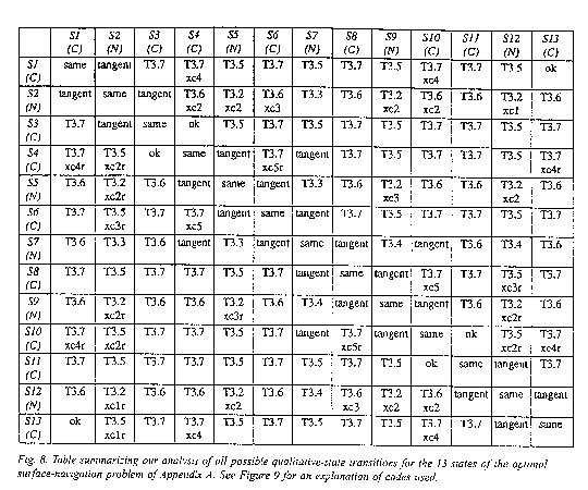
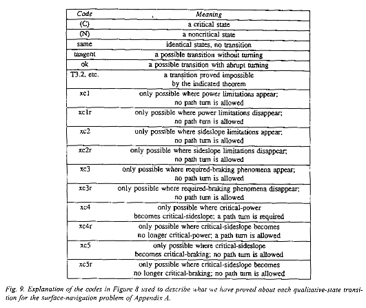
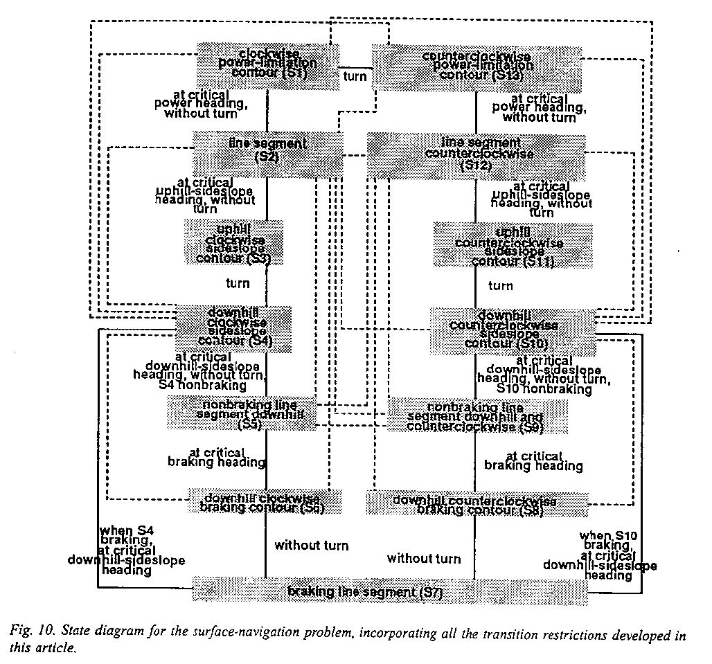
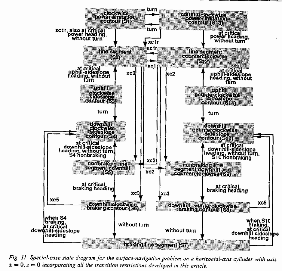
Figs. 8 and 9 summarize the results we have reached about state transitions
for the general surface-navigation problem, and they are represented as a
finite-state diagram in Fig. 9. The involuntary transitions just mentioned are
given "xc" codes in Figs. 8 and 9, and are shown with dotted lines in
Fig. 10. Fig. 11 shows the further simplifications of this diagram that occur
for a horizontal-axis cylinder, following sections 3.4-3.8. Note the edges are
bidirectional in Fig. 10 and unidirectional in Fig. 11: The subcase has
stronger limitations on paths. Note also that both Figs. 10 and 11 have no
designated starting state. This may be set by an initial orientation of the
vehicle if desired.
3.9. Further specific analysis of the missile problem
First consider M1 (M4 can be analyzed analogously). The inclination angle is
fixed at ![]() ,
so to reach a point at height difference
,
so to reach a point at height difference ![]() above the starting point, the path
must have length
above the starting point, the path
must have length ![]() .
This fixed length will have a fixed cost determined from the function of
inclination of section 3.2. Thus it does not matter what path we take to reach
the goal point, as all are of equal cost. To keep the path simple, however, a
helix is sufficient to reach any point in space that can be reached in M1. To
see this, do the following construction: draw a line segment C from the start
to the azimuth projection of the goal into the start plane, then construct a
circular arc in the azimuth plane through these two points such that C is the
chord of the arc and the arc has azimuth-plane length
.
This fixed length will have a fixed cost determined from the function of
inclination of section 3.2. Thus it does not matter what path we take to reach
the goal point, as all are of equal cost. To keep the path simple, however, a
helix is sufficient to reach any point in space that can be reached in M1. To
see this, do the following construction: draw a line segment C from the start
to the azimuth projection of the goal into the start plane, then construct a
circular arc in the azimuth plane through these two points such that C is the
chord of the arc and the arc has azimuth-plane length ![]() ; the arc may subtend more than
360 degrees if necessary. Then the actual path has constant inclination
; the arc may subtend more than
360 degrees if necessary. Then the actual path has constant inclination ![]() and follows this
arc in its azimuth projection. This projection fails to work only when the
length of C is less than
and follows this
arc in its azimuth projection. This projection fails to work only when the
length of C is less than ![]() , in which case no M1 path can reach the
point because the path climbs too fast.
, in which case no M1 path can reach the
point because the path climbs too fast.
Now consider M9. The analysis of section 3.2 rules out turns (abrupt
changes) in inclination for M9. Corollary 3.1 rules out smooth changes in
inclination too, since the space is homogeneous although isotropic. Thus all
paths in M9 have a constant inclination. Furthermore by the last paragraph, a
helix is sufficient to optimally reach any point that is reachable by a path.
Now the cost-per-distance of a path at inclination θ is ![]() , where f is
approximated in section 3.2 by
, where f is
approximated in section 3.2 by ![]() . But this function has no minimum when
. But this function has no minimum when![]() , and is
monotonically decreasing. Hence the steepest possible slope that will reach the
goal is the best.
, and is
monotonically decreasing. Hence the steepest possible slope that will reach the
goal is the best.
4. Reasoning about sequences of three or more states
Besides constraining qualitative-state transitions in a path-planning problem, we can look at possible sequences of three or more qualitative states. We can formulate a cost equation, and differentiate it to find local minima. [Rowe and Kanayama 1994] used this idea to eliminate 26 of 70 possible sequences of three or more states on a cone surface, considerably simplifying the problem. [Rowe, 1992] proves also the following theorem which we will use in the next section.
Theorem 4.1: For the surface-navigation model of Appendix A, assume states S4, S6, S8, and S10 have constant-sign curvature when projected on the azimuth plane in some region of interest within which there are no critical steepnesses as defined in section 3.8. Then no optimal path which includes a braking straight line (state S7) can include any more than one additional behavior, and this additional behavior must be either S4 or S10 where the downhill sideslope heading is braking, and either S6 or S8 where the downhill sideslope heading is nonbraking.
5. Finding behavioral regions from qualitative-state sequences
Once we have defined qualitative states and obtained constraints like those discussed so far, we can enumerate all possible qualitative-state sequences on an optimal path, what we will call behavioral sequences and what qualitative physics calls histories. Good constraints on such sequences make finding the optimal path between two given points a relatively straightforward optimization problem, with variables the arclengths along the path devoted to a particular qualitative state. The major remaining problem is to know which behavioral sequence best takes you from some point P to some point Q. For this we need a behavioral map of the space of start-goal pairs, a partition of it into contiguous behavioral regions such that all pairs in a region have the same optimal qualitative-state sequence. This concept is developed for two-dimensional weighted-region terrain in [Alexander and Rowe 1990]. Since behavioral boundaries tend to be smooth, a behavioral map can most efficiently be represented by describing the boundaries, using standard techniques of graphics [Pavlidis 1982]; standard localization algorithms can then determine what region a point is in. A behavioral region must be distinguished from the definitional region of a behavior, the region within which the behavior can be performed but for which it is not necessarily optimal.
One approach to get a behavioral map is algebraic, as in [Alexander and Rowe 1990]. We first find the definitional regions. For each overlapping pair, we equate their cost formulae, and solve to get the formula of their boundary. We can be more efficient if we can quickly determine that cost bounds say the boundaries do not overlap. For behavior S1 to reach region R, call the cost bounds L1 and U1; for behavior S2 to reach region R, call them L2 and U2. If L2 > U1, S1 is the optimal behavior to R; and if L1 > U2, S2 is optimal. Other methods can also reduce equation-solving, such as careful analysis of multi-state sequences, as we will use in Section 5.1.
A second approach which avoids most algebra is calculate locally-optimal paths to a set of evenly-spaced points for each possible behavior sequence. This method is compared on the cone surface in [Rowe and Kanayama 1994]. Then points can be grouped into approximate regions based on which behavior sequence was best for them. However, this method may require much work to obtain sufficient accuracy in representing boundaries, and has several tricky numeric problems.
A third approach, for problems where the start point is known, is to trace rays representing optimal paths about the start point in an evenly spaced set of directions. Section 5.2 explores this.
5.1. An example behavioral map from algebraic analysis: one case on a cylinder
We can use Fig. 11 and some further simple analysis to get complete
behavioral maps for the horizontal-axis cylinder. Suppose the cylinder has unit
radius, its axis is x = 0 , z = 0 as before, and the starting point is in the
isotropic area at the top of the cylinder at x=0.1 and y=0. Fig. 12 shows the
behavior map we can derive assuming the simplified vehicle-energy model where ![]() is taken as 1.
Fig. 12 shows the top half of the map on a unit cylinder (the bottom half is
mirror-symmetric to this Figure about the x-axis) in an azimuth projection. The
top of the cylinder is x = 0;
is taken as 1.
Fig. 12 shows the top half of the map on a unit cylinder (the bottom half is
mirror-symmetric to this Figure about the x-axis) in an azimuth projection. The
top of the cylinder is x = 0; ![]() are the sides of the cylinder; and
gradient direction is always horizontal. The vertical scale has been compressed
to make the Figure clearer. Each region is labeled with the optimal behavior
necessary to reach points within it from the starting point.
are the sides of the cylinder; and
gradient direction is always horizontal. The vertical scale has been compressed
to make the Figure clearer. Each region is labeled with the optimal behavior
necessary to reach points within it from the starting point.
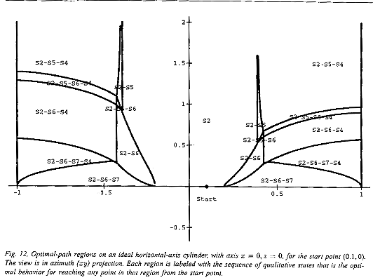
For this situation, definitional regions for each behavior sequence rarely
overlap. When they do, usually the straight line is preferable. For instance,
for points reachable by either S2 or S2-S5, S2 is better because contour S5 curves
and hence is longer. Some of the behavioral-region boundaries represent the
involuntary noncritical-critical transitions of section 3.8, as the S5 to S4
transition from the region labeled S2-S5 to the region labeled S2-S5-S4 in the
top right, and the S5 to S6 transition from that same S2-S5 region to the tiny
region below it labeled S2-S5-S6. Since S2 and S5 behaviors appear as straight
lines, these two boundaries are the locus of points such that the perpendicular
on the surface to a line from the start point has a particular fixed
inclination. This is close to what the differential equations of section 3.5
define. Specifically, boundaries at which downhill-sideslope and braking
phenomena occur on a straight line from ![]() are:
are:
The curves in the lower right and lower left between S2-S6-S7 and S2-S6-S7-S4 regions were plotted parametrically, with parameter the x-coordinate of the point of tangency to the critical-braking contour. The remaining curved boundaries in Fig. 12 are critical-braking contours (between S2 and S2-S6) and critical-sideslope (those above and below S2-S5-S6-S4). We approximated the integrals for plotting by five-term and three-term series respectively.
Fig. 12 shows only the case where the start point is in the top unconstrained area of the cylinder. There are seven more behavioral maps possible, for every combination of presence/absence of the three critical headings at a start point. Nonetheless, we can obtain these maps far more easily using the general methods of this paper than with the ad-hoc methods of [Rowe and Kanayama 1994], which required 40 theorems for the vertical-axis cone.
5.2. Example behavioral maps approximated by ray-tracing
We also wrote a ray-tracing program to find sample optimal paths for arbitrary surfaces with the surface-traversal model of Appendix A. Given two optimal paths P1 and P2 from some start point S, paths from S to points lying between P1 and P2 can be interpolated between corresponding segments of P1 and P2; with enough optimal paths radiating from S, a good path can be interpolated to anywhere. We used the state diagram of Fig. 10 to restrict possible optimal-path behavior, plus the finite-state constraints mentioned. We also used the full unsimplified vehicle model, which we did not do in previous papers. The program propagates paths outward like uniform-grid wavefront propagation, but the path tips are not restricted to a finite set of points, and turns and headings are not restricted to a finite set of angles. This means the paths are far closer to optimum than those obtainable from conventional wavefront propagation.
Our ray-tracing works as a branch-and-bound search about the start point but without an explicit goal, gradually extending paths in permissible directions that are initially spaced evenly. We model the surface as a polyhedron with triangular facets that exactly fit evenly-spaced elevation data. The state at any point on a path can be characterized by a position, a heading, and a qualitative state. At each path tip, we compute permissible state transitions from Fig. 10. For each transition, we then compute the associated heading of the new state using the gradient of the surface there. The path is then extended at this heading until it reaches the next edge of a triangular facet, which becomes the new path tip. This creates a tree of paths rooted at the start point.
Critical states usually permit two transitions: to a tangent line for a neighboring noncritical state, and to a counterpart critical state. To reduce branching, we required that transitions from critical states cannot occur after very short path segments, and not when a similar transition could also be made one step earlier. We also added a small amount of cost proportional to the sum of the magnitudes of the turn angles in the path, to break ties between same-cost paths. Before adding any path extension to the tree, we also check it against the rest of the tree for intersections or near-intersections with nearby segments. If one is found, we compute the cost to it for each path, and terminate the more expensive path there. This quickly prunes many suboptimal paths, since tree branches tend to be closely spaced.
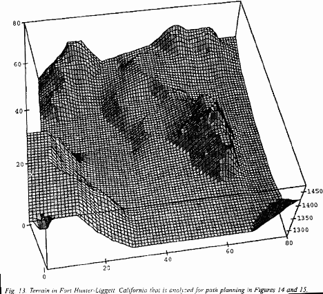
Fig. 13 shows terrain in Fort Hunter-Liggett, California, at 35 degrees
57'30" N and 121 degrees 16'30" W, part of which (the lower right
quadrant, inverted) was previously analyzed for path planning in Fig. 13 of
[Rowe and Ross 1990]. The vertical scale is exaggerated; vertical units are feet
above sea level, and horizontal grid marks every 12.5 meters, so the horizontal
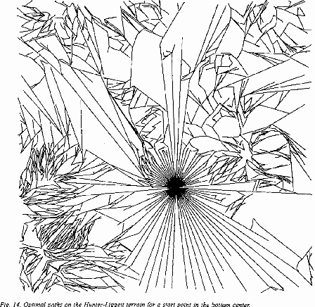
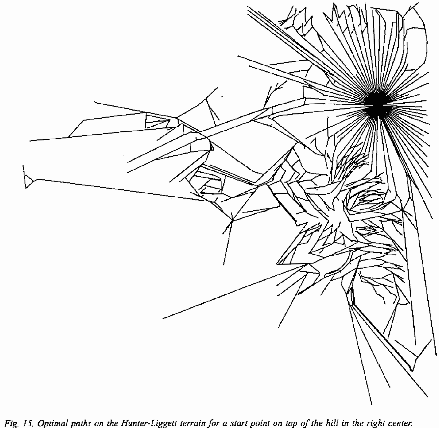
area shown is about 3600 by 3600 feet. Figs. 14 and 15 show the results on this
terrain of an uncompiled Quintus-Prolog version 3.1 implementation of our
propagation algorithm on a Sun Sparc workstation. For Fig. 14, the start point
was in the lower middle of Fig. 13; for Fig. 15, in the top right. The lines
are the optimal paths found. Regions of sharp turns are regions where
switchbacks or slaloming between critical headings is necessary on optimal
paths. Short suboptimal "spur" paths were found at many places, due
to the limited number of starting path directions; these could have been
reduced by increasing the number of directions or could have been eliminated by
a post-processor. Fig. 14 took 544 minutes of cpu time and 4.46 megabytes of
main memory; Fig. 15 took 111 minutes and 2.46 megabytes of main memory.
Despite these time and space requirements, our implementation is considerably faster than the program of [Rowe and Ross 1990] on the same problems, a program which required about 22 times as many lines of code to find just a single path from a start point to a goal. This dramatic improvement is due to the elimination by our theory of a considerable number of state sequences. Processing times in [Rowe and Ross 1990] varied widely, but 15 minutes was typical for experiments on a slightly slower machine than the Sun Sparc; terrain there was at most 31 regions, whereas the terrain for Figs. 14-15 was modelled by 3200 triangular regions. Thus our program runs much faster per optimal path.
6. Conclusion
We have developed a general theory for simplifying optimal-path planning with moderately anisotropic cost-per-distance functions, a theory exploiting qualitative state distinctions in a rigorous way. Now anisotropism need not be ignored or dismissed cavalierly from path planning, as we have provided theorems for when it is well-behaved enough to guarantee certain valuable features of the optimal path. While our approach cannot handle every anisotropic problem, it can handle quite a large class, including the important one of surface navigation in the presence of gravity and friction effects, a problem which has never been solved in general. Implementation of our ideas on this latter problem has demonstrated much better performance than the 22-times longer program of [Rowe and Ross 1990] on similar problems. We are hopeful that our work will provide useful tools for future path planning.
7. References
Alexander, R. S. and Rowe, N. C. 1990 (May). Path planning by optimal-path-map construction for homogeneous-cost two-dimensional regions. Proceedings of IEEE International Conference on Robotics and Automation, Cincinnati, OH, pp. 1924-1929.
Bekker, M. G. 1969. Introduction to Terrain-Vehicle Systems. Ann Arbor, MI: University of Michigan Press.
Forbus, K. 1988. Qualitative physics: past, present, and future. Exploring Artificial Intelligence, ed. H. Shrobe. San Mateo, CA: Morgan Kaufmann, pp. 239-296.
Gaw, D. and Meystel, A. 1986 (April). Minimum-time navigation of an unmanned mobile robot in a 2-1/2D world with obstacles. Proceedings of the IEEE Conference on Robotics and Automation. New York: IEEE Press, 1670-1677.
Holmes, P. A. and Jungert, E. 1988 (August, Vienna). Shortest paths in a digitised map using a tile-based data structure. Proceedings of the Third International Conference on Engineering Graphics and Descriptive Geometry. New York: IEEE Press, vol. I, pp. 238-245.
Klein, C. A. and Miklos, T. A. 1991 (August). Spatial robot isotropy. International Journal of Robotics Research, 10 (4), 426-439.
Kuipers, B. 1986. Qualitative simulation. Artificial Intelligence, 29, 289-388.
Liu, J. and Daneshmend, L. K. 1991 (April, Sacramento CA USA). Qualitative analysis of task kinematics for compliant motion planning. Proceedings of the 1991 IEEE International Conference on Robotics and Automation. New York: IEEE Press, pp. 1258-1265.
Mitchell, J. S. B. and Keirsey, D. 1984. Planning strategic paths through variable terrain data. SPIE, Applications of Artificial Intelligence, volume 485, 172-179.
Mitchell, J. S. B., Mount, D. M., and Papadimitriou, C. H. 1987 (August). The discrete geodesic problem. SIAM Journal on Computing, 16 (4), 647-668.
Papadakis, N. A. and Perakis, A. N. 1990 (May-June). Deterministic minimal time vessel routing. Operations Research, 38(3), 426-438.
Parodi, A. M. 1985. Multi-goal real-time global path planning for an autonomous land vehicle using a high-speed graph search processor. Proceedings of the 1985 IEEE Conference on Robotics and Automation. New York: IEEE Press, pp. 161-167.
Pavlidis, T. 1982. Graphics and Image Processing. Rockville, MD: Computer Science Press.
Rowe, N. C. 1992 (September). Obtaining optimal mobile-robot paths with non-smooth anisotropic cost functions using qualitative-state reasoning. Technical report NPSCS-92-012, Naval Postgraduate School.
Rowe, N. C. and Kanayama, Y. 1994 (October). Minimum-energy paths on a vertical-axis cone with anisotropic friction and gravity effects. International Journal of Robotics Research, 13(5), 408-432.
Rowe, N. C. and Lewis, D. H. 1989 (January). Vehicle path-planning using optics analogs for optimizing visibility and energy cost. Proceedings of the NASA Conference on Space Telerobotics. Pasadena, CA: NASA Jet Propulsion Laboratory Publication 89-7, vol. IV, pp. 217-226.
Rowe, N. C. and Richbourg, R. F. 1990 (December). An efficient Snell's-law method for optimal-path planning across multiple homogeneous-cost regions. International Journal of Robotics Research, 9(6), 48-56.
Rowe, N. C. and Ross, R. S. 1990. Optimal grid-free path planning across arbitrarily-contoured terrain with anisotropic friction and gravity effects. IEEE Transactions on Robotics and Automation, RA-6 (3), 540-553.
Rula, A. A. and Nuttall, C. J. 1971 (July). An analysis of ground mobility models (ANAMOB). Technical Report M-71-4, U.S. Army Engineer Waterways Experiment Station, Vicksburg, MS.
Sharir, M. and Schorr, A. 1986 (February). On shortest paths in polyhedral spaces. SIAM Journal of Computing, 15(1), 193-215.
Wrenn, L. 1989 (June). Three-dimensional route planning for a cruise missile for minimal detection by observers. M.S. thesis, Computer Science Department, U. S. Naval Postgraduate School, (also technical report NPS52-090-002).
8. Appendix A: A model of surface traversal with gravity and friction effects
We summarize here the model used in [Rowe and Ross 1990] and [Rowe and
Kanayama 1994] for a vehicle of negligible size and zero turn radius (our
meaning of "high-level" planning) moving on a smooth surface with
constant coefficient of friction ![]() . We assume that the vehicle is affected
only by propulsion, gravity, and a friction force proportional to the normal
force on the surface, and that the vehicle has no net acceleration between
start and goal. [Rowe and Ross 1990] shows that it is mathematically equivalent
to find minimum-energy paths in the azimuth (map) projection of the surface
provided the surface is never vertical. Letting
. We assume that the vehicle is affected
only by propulsion, gravity, and a friction force proportional to the normal
force on the surface, and that the vehicle has no net acceleration between
start and goal. [Rowe and Ross 1990] shows that it is mathematically equivalent
to find minimum-energy paths in the azimuth (map) projection of the surface
provided the surface is never vertical. Letting ![]() be the azimuth heading clockwise of
the uphill azimuth direction, the path inclination on a surface with gradient
inclination
be the azimuth heading clockwise of
the uphill azimuth direction, the path inclination on a surface with gradient
inclination ![]() is
is
![]() . Then
since work need only be done against gravity and friction with this model, the
cost-per-distance at some azimuth heading on a locally-flat surface is
. Then
since work need only be done against gravity and friction with this model, the
cost-per-distance at some azimuth heading on a locally-flat surface is ![]() , or zero if this
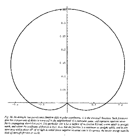
formula is negative. Fig. 16 plots this cost-per-distance function in polar
coordinates for a surface angle of inclination of
, or zero if this
formula is negative. Fig. 16 plots this cost-per-distance function in polar
coordinates for a surface angle of inclination of ![]() radians, a coefficient of friction 0.15,
and with uphill as north on the page. We shall always measure azimuth clockwise
of the uphill azimuth direction, so east in Fig. 16 is 90 degrees and west is
270 (or -90) degrees. Observe that the Fig. 16 cost-per-distance function is at
a maximum for traversal straight uphill (0 degrees azimuth heading), and is
zero between azimuth headings of 135 and 215 (despite the superficial
similarity of the curve to a cardioid), when the vehicle must brake to prevent
increasing speed to an unsafe amount.
radians, a coefficient of friction 0.15,
and with uphill as north on the page. We shall always measure azimuth clockwise
of the uphill azimuth direction, so east in Fig. 16 is 90 degrees and west is
270 (or -90) degrees. Observe that the Fig. 16 cost-per-distance function is at
a maximum for traversal straight uphill (0 degrees azimuth heading), and is
zero between azimuth headings of 135 and 215 (despite the superficial
similarity of the curve to a cardioid), when the vehicle must brake to prevent
increasing speed to an unsafe amount.
[Rowe and Ross 1990] then shows that if we take ![]() , a reasonable approximation on
most real-world surfaces, the cost-per-distance of nonbraking traversal from a
point is K, independent of path inclination, and the cost-per-distance of
braking traversal is
, a reasonable approximation on
most real-world surfaces, the cost-per-distance of nonbraking traversal from a
point is K, independent of path inclination, and the cost-per-distance of
braking traversal is ![]() . (If
. (If ![]() varies on a surface, the
surface can be subdivided into areas in which
varies on a surface, the
surface can be subdivided into areas in which ![]() is constant and each analyzed
separately, as in the weighted-region problem [Rowe and Richbourg 1990]). We
will show in section 3.3 that the assumption that the ratio of cosines is 1 is
not necessary to obtain the results of those earlier papers, though it does
change a little the shape of some of the paths as per section 3.6. We will call
the model that assumes
is constant and each analyzed
separately, as in the weighted-region problem [Rowe and Richbourg 1990]). We
will show in section 3.3 that the assumption that the ratio of cosines is 1 is
not necessary to obtain the results of those earlier papers, though it does
change a little the shape of some of the paths as per section 3.6. We will call
the model that assumes ![]() the "simplified model".
the "simplified model".
The simplified model implies that traversal requires vehicle braking if the
path slopes more than ![]() downward,
downward, ![]() the coefficient of
friction, and the unsimplified model implies
the coefficient of
friction, and the unsimplified model implies ![]() . On a surface whose gradient inclination
is more than this, the two azimuth headings bounding the heading range in which
braking occurs will be called the critical braking headings
. On a surface whose gradient inclination
is more than this, the two azimuth headings bounding the heading range in which
braking occurs will be called the critical braking headings ![]() and
and ![]() . If the surface
gradient inclination at some point is
. If the surface
gradient inclination at some point is ![]() ,
, ![]() from three-dimensional geometry for
the simplified model. For the unsimplified model, the formula is only a little
more complicated:
from three-dimensional geometry for
the simplified model. For the unsimplified model, the formula is only a little
more complicated: ![]() .
.
Similar critical headings arise from power limitations and stability
phenomena. Suppose the vehicle has insufficient power to negotiate an uphill
slope of more than ![]() ,
the critical power inclination. Then at any point on the surface where
the gradient angle is steeper than
,
the critical power inclination. Then at any point on the surface where
the gradient angle is steeper than ![]() , there are two critical power
headings
, there are two critical power
headings ![]() and
and
![]() where
where
![]() , such that
the vehicle cannot negotiate an azimuth heading
, such that
the vehicle cannot negotiate an azimuth heading ![]() if
if ![]() . Sideslope stability problems,
on the other hand, occur when the tilt of the vehicle perpendicular to
the direction of travel exceeds a particular critical sideslope inclination
. Sideslope stability problems,
on the other hand, occur when the tilt of the vehicle perpendicular to
the direction of travel exceeds a particular critical sideslope inclination ![]() . On a surface
whose gradient inclination is more than this
. On a surface
whose gradient inclination is more than this ![]() , there are two symmetric ranges of
impermissible-sideslope vehicle headings, one clockwise of uphill and one
counterclockwise. By geometry, the four critical azimuth headings for these two
heading ranges are
, there are two symmetric ranges of
impermissible-sideslope vehicle headings, one clockwise of uphill and one
counterclockwise. By geometry, the four critical azimuth headings for these two
heading ranges are ![]() ,
,
![]() ,
, ![]() , and
, and ![]() where
where ![]() . Note
. Note ![]() if both exist
since
if both exist
since ![]() and
and
![]() . Note uphill
travel is possible only if
. Note uphill
travel is possible only if ![]() . The formulae for these headings
are the same for both the simplified and unsimplified models.
. The formulae for these headings
are the same for both the simplified and unsimplified models.
These critical azimuth headings define "landmark values"
articulating ranges of heading; these ranges define qualitative distinctions between
states during path traversal. Formally, a state for our vehicle model shall be
a triple (<x-coordinate>, <y-coordinate>, <azimuth-angle-clockwise-from-uphill>);
then its corresponding qualitative state is the azimuth-heading range
consistent with that heading, that x-coordinate, and that y-coordinate. (The
range can depend on x and y because gradient magnitude can vary over the
surface.) We will only consider here landmark values that are headings, either
of the vehicle or surface at a point, since we assume a terrain area in which ![]() is constant. Our
landmark values will not be evenly spaced as in the qualitative path planning
in configuration space of [Liu and Daneshmend 1991], but will be the meaningful
headings of the domain, as this will permit fewer of them and better domain
representation. So for our vehicle model, we will define the following
qualitative states, where
is constant. Our
landmark values will not be evenly spaced as in the qualitative path planning
in configuration space of [Liu and Daneshmend 1991], but will be the meaningful
headings of the domain, as this will permit fewer of them and better domain
representation. So for our vehicle model, we will define the following
qualitative states, where ![]() is the azimuth angle measured
clockwise from uphill with defined range
is the azimuth angle measured
clockwise from uphill with defined range ![]() :
:
S1.
if power restrictions apply
S2.if both power and sideslope restrictions apply;
orif only power and braking restrictions apply;
orif sideslope but no power restrictions apply;
orif only power restrictions apply;
orif only braking restrictions apply;
or any heading if no restrictions apply
S3.when sideslope restrictions apply
S4.when sideslope restrictions apply (note can be braking or nonbraking)
S5.when sideslope and braking restrictions apply and

orwhen sideslope and but no braking restrictions apply
S6.when braking restrictions apply and

S7.when braking restrictions apply
We will also define S8 to the negative-counterpart state (where all angles in the definition are negated) to S6; S9 to S5; S10 to S4; S11 to S3; S12 to S2 (except not applying where S2 also applies); and S13 to S1.
Besides Figs. 1-3, other cases can be created from them by deleting from each of these the power-limitation states S1 and S13, then merging S12 into S2; or by deleting the braking states S6, S7, and S8, merging S9 into S5; or by deleting the sideslope states as in going from Fig. 1 to Fig. 3. Or more than one deletion can be applied; the above definitions state what occurs.
Path analysis is simplified on certain surfaces. Thus it is desirable to model complex surfaces as a set of patches of simpler surfaces, like polyhedral faces in [Rowe and Ross 1990], or cone pieces in [Rowe and Kanayama 1994]; surface-modeling work from graphics can help.
9. Appendix B: A model of missile flight
Simplifying matters to treat the missile as a point, a missile state can be
characterized by a position, an azimuth heading ![]() , an inclination angle (positive upwards)
, an inclination angle (positive upwards)
![]() , and a
derivative with respect to path length of the azimuth heading
, and a
derivative with respect to path length of the azimuth heading ![]() . Assume that the
missile's starting point is fixed, but its starting orientation is
unconstrained. Missiles like the cruise missiles studied in [Rowe and Lewis
1989] and [Wrenn 1989] show that the power necessary to maintain constant-speed
flight has a positive second derivative with respect to
. Assume that the
missile's starting point is fixed, but its starting orientation is
unconstrained. Missiles like the cruise missiles studied in [Rowe and Lewis
1989] and [Wrenn 1989] show that the power necessary to maintain constant-speed
flight has a positive second derivative with respect to ![]() , and let us assume
cost-per-distance is independent of
, and let us assume
cost-per-distance is independent of ![]() . As the power required increases
monotonically with angle, a particular missile can have a maximum
. As the power required increases
monotonically with angle, a particular missile can have a maximum ![]() of
of ![]() with a
corresponding maximum thrust; and a missile can have a minimum
with a
corresponding maximum thrust; and a missile can have a minimum ![]() (or maximum dive
angle) of
(or maximum dive
angle) of ![]() ,
beyond which it would accelerate to speeds too fast to safely control. Missiles
generally have a turn radius minimum for turns in
,
beyond which it would accelerate to speeds too fast to safely control. Missiles
generally have a turn radius minimum for turns in ![]() , which we will call
, which we will call ![]() . (We oversimplify for
demonstration purposes.) Taking all this into account, there are nine
qualitative states for missile flight in homogeneous space:
. (We oversimplify for
demonstration purposes.) Taking all this into account, there are nine
qualitative states for missile flight in homogeneous space:
M1.
and
provided power restrictions apply
M2.and
provided power restrictions apply
M3.and

M4.and
provided downhill restrictions apply
M5.and
provided downhill restrictions apply
M6. like M2 but for
M7. like M3 but for
M8. like M5 but for
M9. All other permissible states
List of figures for Rowe, Obtaining Optimal Mobile-Robot Paths with Non-Smooth Anisotropic Cost Functions Using Qualitative-State Reasoning
Fig. 1: A summary of the thirteen qualitative states in the most general form of the surface-traversal problem. The picture represents a view from above (azimuth view) of an agent at a point on a surface, and illustrates the possible directions that agent could travel from that point. Uphill is straight north. For other surface slopes and coefficients of friction, the diagram may need to be replaced by Fig. 2 or Fig. 3.
Fig. 2: A summary of the nine qualitative states in the surface-traversal
problem for the case in which the downhill sideslope inclination ![]() is also a
braking inclination. In this case, states S5, S6, S8, and S9 disappear. The
picture represents a view from above (azimuth view) of an agent on a surface,
and illustrates the possible directions that agent could travel; uphill is
straight north.
is also a
braking inclination. In this case, states S5, S6, S8, and S9 disappear. The
picture represents a view from above (azimuth view) of an agent on a surface,
and illustrates the possible directions that agent could travel; uphill is
straight north.
Fig. 3: A summary of the seven qualitative states in the surface-traversal problem for the case in which there are no sideslope-overturn limitations. Then states S3, S4, S10, and S11 disappear, S5 is merged into S2, and S9 is merged into S12. The picture represents a view from above (azimuth view) of an agent on a surface, and illustrates the possible directions that agent could travel; uphill is straight north.
Fig. 4: A summary of the four unique-path qualitative states (M2, M5, M6, and M8) for the missile problem. These can be interpreted as paths of a missile starting at (0,0,0). M2 and M6 begin with an upward tilt, and M5 and M8 begin with a downward tilt; M2 and M5 curve rightward, and M6 and M8 curve leftward. All paths are arcs of helices.
Fig. 5: Illustration for Theorem 3.1.
Fig. 6: Graph of the criterion function needed for Theorem 3.1, ![]() for the
unsimplified surface navigation problem of Appendix A,
for the
unsimplified surface navigation problem of Appendix A, ![]() , on a surface with a gradient
inclination of 30 degrees. Note the function appears always positive with
plenty of room to spare.
, on a surface with a gradient
inclination of 30 degrees. Note the function appears always positive with
plenty of room to spare.
Fig. 7: Example of power-limitation contours (for qualitative states S1 and
S13) on the surface of a cylinder with unit radius and axis x = 0 , z = 0,
viewed from above in azimuth (xy) projection. The starting point for both
contours is (0.5,0), and both run left. The critical power inclination ![]() was 0.2, and
note both contours terminate with x near there because the slope to the left of
0.2 is too shallow to sustain a power limitation.
was 0.2, and
note both contours terminate with x near there because the slope to the left of
0.2 is too shallow to sustain a power limitation.
Fig. 8: Table summarizing our analysis of all possible qualitative-state transitions for the thirteen states of the optimal surface navigation problem of Appendix A. See Fig. 10 for an explanation of codes used.
Fig. 9: Explanation of the codes in Fig. 9 used to describe what we have proved about each qualitative-state transition for the surface-navigation problem of Appendix A.
Fig. 10: State diagram for the surface-navigation problem, incorporating all the transition restrictions developed in this paper.
Fig. 11: Special-case state diagram for the surface-navigation problem on a horizontal-axis cylinder with axis x = 0 , z = 0, incorporating all the transition restrictions developed in this paper.
Fig. 12: Optimal-path regions on an ideal horizontal-axis cylinder, with axis x = 0 , z = 0, for the start point (0.1,0). The view is in azimuth (xy) projection. Each region is labeled with the sequence of qualitative states that is the optimal behavior for reaching any point in that region from the start point.
Fig. 13: Terrain in Fort Hunter-Liggett, California that is analyzed for path planning in Figs. 14 and 15.
Fig. 14: Optimal paths on the Hunter-Liggett terrain for a start point in the bottom center.
Fig. 15: Optimal paths on the Hunter-Liggett terrain for a start point on top of the hill in the right center.
Fig. 16: An example cost-per-distance function ![]() in polar coordinates,
in polar coordinates, ![]() the traversal
direction. Such functions give the cost per unit of distance traversed in the
neighborhood of a particular point, and represent equicost wavefronts
propagating about that point. This particular one is for a surface of
inclination 0.2 radians, where uphill is straight north, and where the
coefficient of friction is 0.15. Note that the function is a maximum at
straight uphill, and is a constant zero within about 45 degrees of straight
downhill (since negative traversal cost is dangerous, the excess energy must be
bled off through friction or work).
the traversal
direction. Such functions give the cost per unit of distance traversed in the
neighborhood of a particular point, and represent equicost wavefronts
propagating about that point. This particular one is for a surface of
inclination 0.2 radians, where uphill is straight north, and where the
coefficient of friction is 0.15. Note that the function is a maximum at
straight uphill, and is a constant zero within about 45 degrees of straight
downhill (since negative traversal cost is dangerous, the excess energy must be
bled off through friction or work).


