2.2 Separately excited DC motor operation and control, Figure 7
![]() Figure 7 In this laboratory two separate buck converters are used to control the field and the armature voltage. The field voltage is generated by the buck converter of leg B in the Semikron power module shown in Figure 4. The duty cycle for the IGBT B+ is set to a constant. The output of leg A buck converter is applied to the armature of the DC motor as shown in Figure 1. When the “IR compensation” option is off, the duty cycle is set by the “speed” command defined by the user. When the “IR compensation” feature is on, the gate drive signal for the IGBT A+ is generated as shown in the diagram of Figure 7. By adding the ra_estIa_meas term to the commanded voltage, the speed of the DC motor is no longer affected by changes in the load.
Figure 7 In this laboratory two separate buck converters are used to control the field and the armature voltage. The field voltage is generated by the buck converter of leg B in the Semikron power module shown in Figure 4. The duty cycle for the IGBT B+ is set to a constant. The output of leg A buck converter is applied to the armature of the DC motor as shown in Figure 1. When the “IR compensation” option is off, the duty cycle is set by the “speed” command defined by the user. When the “IR compensation” feature is on, the gate drive signal for the IGBT A+ is generated as shown in the diagram of Figure 7. By adding the ra_estIa_meas term to the commanded voltage, the speed of the DC motor is no longer affected by changes in the load.
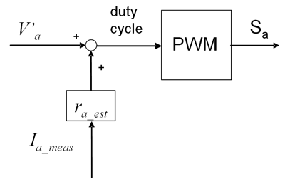
Figure 7: IGBT A+ gate drive signal generation with IR compensation